36 Micro Motion
®
Model D and DT Sensors Instruction Manual
Wiring continued
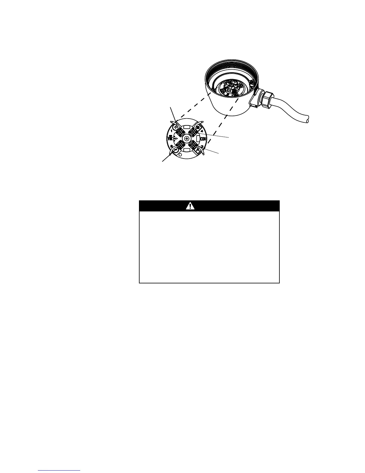
Core processor terminals
Sensor grounding
Ground the sensor and transmitter independently.
The sensor can be grounded via the piping if the joints in the pipeline are
ground-bonded. If the sensor is not grounded via the piping, connect a
ground wire to the internal or external grounding screw, which is located
on the core processor or junction box.
If national standards are not in effect, follow these guidelines:
• Use copper wire, 14 AWG (2,5 mm
2
) or larger wire size for grounding.
• Keep all ground leads as short as possible, less than 1 ohm
impedance.
• Connect ground leads directly to earth, or follow plant standards.
Refer to the transmitter documentation for instructions on grounding the
transmitter.
Improper grounding could cause measurement error.
To reduce the risk of measurement error:
• Ground the flowmeter to earth, or follow ground network
requirements for the facility.
• For installation in an area that requires intrinsic safety,
refer to Micro Motion hazardous approval documentation,
shipped with the sensor or available from the Micro
Motion web site.
• For hazardous area installations in Europe, refer to
standard EN 60079-14 if national standards do not apply.