Safety
Information
Product
information
Mechanical
Installation
Electrical
installation
Getting
started
Basic
parameters
Running the
motor
Optimization
SMARTCARD
operation
Onboard
PLC
Advanced
parameters
Technical
data
Diagnostics
UL
information
Mentor MP User Guide 103
Issue: 3 www.controltechniques.com
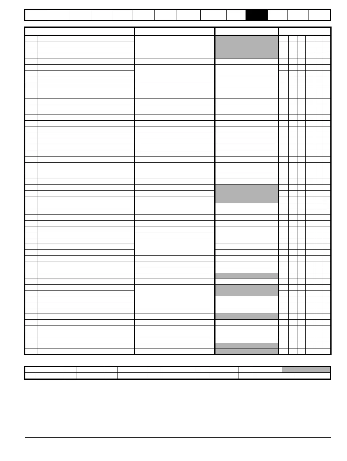
Parameter
Range(
Ú) Default(Ö)
Type
3.01 Final speed reference {di04, 0.39}
±SPEED_MAX rpm
RO Bi FI NC PT
3.02 Speed feedback {di05, 0.40} RO Bi FI NC PT
3.03 Speed error RO Bi FI NC PT
3.04 Speed controller output {di06, 0.41} ±Torque_prod_current_max % RO Bi FI NC PT
3.05 Zero speed threshold 0 to 200 rpm 30 RW Uni US
3.06 At speed lower limit
0 to 10,000 rpm
5
RW Uni US
3.07 At speed upper limit RW Uni US
3.08 Overspeed threshold 0RWUniUS
3.09 Absolute ‘at speed’ detect OFF (0) or On (1) OFF (0) RW Bit US
3.10
Speed controller proportional gain
(Kp1)
{SP01, 0.61} 0.0 to 6.5535 (1 / rad/s)) 0.0300 RW Uni US
3.11 Speed controller integral gain (Ki1) {SP02, 0.62} 0 to 655.35 (s / rad/s)) 0.10 RW Uni US
3.12
Speed controller differential
feedback gain (Kd1)
{SP03, 0.63} 0 to 0.65535 (1/s / rad/s)) 0.00000 RW Uni US
3.13 Speed controller proportional gain (Kp2) 0.0 to 6.5535 (1 / rad/s)) 0.0300 RW Uni US
3.14 Speed controller integral gain (Ki2) 0 to 655.35 (s / rad/s)) 0.10 RW Uni US
3.15 Speed controller differential feedback gain (Kd2) 0 to 0.65535 (1/s / rad/s)) 0.00000 RW Uni US
3.16 Speed controller gain select OFF (0) or On (1) OFF (0) RW Bit US
3.17 Speed controller set-up method 0 to 2 0 RW Uni US
3.18 Motor and load inertia
0.0 to 90.00000 kg m
2
0.00000 RW Uni US
3.20 Bandwidth 0 to 50 Hz 1 RW Uni US
3.21 Damping factor 0.0 to 10.0 1.0 RW Uni US
3.22 Hard speed reference
-MAX_SPEED_REF to
MAX_SPEED_REF rpm
0.0 RW Bi US
3.23 Hard speed reference selector OFF (0) or On (1) OFF (0) RW Bit US
3.26 Speed feedback selector {Fb01, 0.71} 0 to 5 5 RW Txt US
3.27 Drive encoder speed feedback {Fb09, 0.79} ±10,000.0 rpm
RO Bi FI NC PT
3.28 Drive encoder revolution counter ±32,768 revolutions RO Bi FI NC PT
3.29 Drive encoder position
0 to 65,535 1/2
16
ths of a revolution
RO Uni FI NC PT
3.31 Drive encoder marker position reset disable
OFF (0) or On (1) OFF (0)
RW Bit US
3.32 Drive encoder marker flag RW Bit NC
3.33 Drive encoder turn bits 0 to 16 16 RW Uni US
3.34 Drive encoder lines per revolution {Fb05, 0.75} 1 to 50,000 1024 RW Uni US
3.35 Drive encoder marker mode 0 to 1
0
RW Uni US
3.36 Drive encoder supply voltage {Fb06, 0.76} 0 to 3 RW Txt US
3.38 Drive encoder type {Fb07, 0.77}
0 to 2
RW Txt US
3.39 Drive encoder termination select {Fb08, 0.78} 1RWUniUS
3.40 Drive encoder error detection level 0RWUniUS
3.42 Drive encoder filter 0 to 5 (0 to 16ms) 2 RW Txt US
3.43 Maximum drive encoder reference 0 to 10,000 rpm 1000 RW Uni US
3.44 Drive encoder reference scaling 0 to 4.000 1.000 RW Uni US
3.45 Drive encoder reference ±100.0%
RO Bi FI NC PT
3.46 Drive encoder reference destination 0 to 22.99 0.00 RW Uni DE PT US
3.47 Re-initialise position feedback
OFF (0) or On (1)
RW Bit NC
3.48 Position feedback initialised RO Bit NC PT
3.49 Full motor object electronic nameplate transfer
OFF (0)
RW Bit US
3.50 Position feedback lock RW Bit NC
3.51 Tachometer voltage rating {Fb02, 0.72} 0 to 300.00 v/1000rpm Eur:60.00, USA 50.00 RW US
3.52 Tachometer speed feedback {Fb04, 0.74} ±SPEED_MAX rpm
RO Bi FI NC PT
3.53 Tachometer input mode {Fb03, 0.73} 0 to 2 0 (DC) RW Txt US
3.54 Encoder direction
OFF (0) or On (1) OFF (0)
RW Bit US
3.55 Select estimated speed on feedback loss RW Bit US
3.56 Speed feedback loss window 0 to 100.0% 20.0% RW US
3.57 Estimated speed has been automatically selected OFF (0) or On (1)
RO Bit
3.58 Speed feedback percentage ±100.0%
RO NC PT
RW Read / Write RO Read only Uni Unipolar Bi Bi-polar Bit Bit parameter Txt Text string
FI Filtered DE Destination NC Not copied RA Rating dependent PT Protected US User save PS Power down save