Safety
Information
Product
information
Mechanical
Installation
Electrical
installation
Getting
started
Basic
parameters
Running the
motor
Optimization
SMARTCARD
operation
Onboard
PLC
Advanced
parameters
Technical
data
Diagnostics
UL
information
164 Mentor MP User Guide
www.controltechniques.com Issue: 3
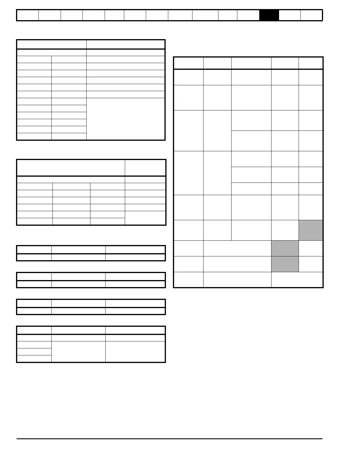
Table 12-37 Mentor MP size 1 drive thyristor I
2
t ratings for
semiconductor fusing
Table 12-38 Mentor MP size 2 drive thyristor I
2
t ratings for
semiconductor fusing
12.2.3 Torque settings
Table 12-39 Drive control, status relay and encoder terminal data
Table 12-40 Drive auxiliary and machine armature terminal data
Table 12-41 Drive power stage terminals
Table 12-42 Drive power stage terminals on size 2 drives
12.2.4 Electromagnetic compatibility (EMC)
This is a summary of the EMC performance of the drive. For full details,
refer to the Mentor MP EMC data sheet which can be obtained from the
supplier of the drive.
Table 12-43 Immunity compliance
1
See section 4.9.4 Surge immunity of control circuits - long cables and
connections outside a building on page 47 for control ports for possible
requirements regarding grounding and external surge protection.
Model
Thyristor I
2
t (A
2
s)
Auxiliary 400
MP25A4 MP25A5 1030
MP45A4 MP45A5 3600
MP75A4 MP75A5 15000
MP25A4(R) MP25A5(R) 1030
MP45A4(R) MP45A5(R) 3600
MP75A4(R) MP75A5(R) 15000
MP105A4 MP105A5
80000
MP155A4 MP155A5
MP210A4 MP210A5
MP105A4(R) MP105A5(R)
MP155A4(R) MP155A5(R)
MP210A4(R) MP210A5(R)
Model
Thyristor I
2
t
(A
2
s)
Auxiliary 400
MP350A4(R) MP420A4(R) MP550A4(R) 320000
MP350A6(R) MP470A5(R) MP470A6(R) 281000
MP700A4(R) MP825A4(R) MP900A4(R) 1050000
MP700A6(R) MP825A5(R) MP825A6(R) 1200000
MP1200A4(R) MP1200A5(R) MP1200A6(R)
2720000
MP1850A4(R) MP1850A5(R) MP1850A6(R)
Model Connection type Torque setting
All Plug-in terminal block 0.5 Nm 0.4 lb ft
Model Connection type Torque setting
All Terminal block 0.5 Nm 0.4 lb ft
Model Connection type Torque setting
All M8 stud 10 Nm 7.4 lb ft
Model Connection type Torque setting
Size 2A M10 stud 15 Nm (11.06 lb ft)
Size 2B
M12 stud 30 Nm (22.12 Ib ft)Size 2C
Size 2D
Standard
Type of
immunity
Test specification Application Level
IEC 61000-4-2
EN 61000-4-2
Electrostatic
discharge
6kV contact
discharge
8kV air discharge
Module
enclosure
Level 3
(industrial)
IEC 61000-4-3
EN 61000-4-3
Radio
frequency
radiated field
10V/m prior to
modulation
80 - 1000MHz
80% AM (1kHz)
modulation
Module
enclosure
Level 3
(industrial)
IEC 61000-4-4
EN 61000-4-4
Fast transient
burst
5/50ns 2kV transient
at 5kHz repetition
frequency via
coupling clamp
Control lines
Level 4
(industrial
harsh)
5/50ns 2kV transient
at 5kHz repetition
frequency by direct
injection
Power lines
Level 3
(industrial)
IEC 61000-4-5
EN 61000-4-5
Surges
Common mode 4kV
1.2/50μs waveshape
AC supply
lines:
line to ground
Level 4
Differential mode 2kV
1.2/50μs waveshape
AC supply
lines:
line to line
Level 3
Lines to ground
Signal ports to
ground
1
Level 2
IEC 61000-4-6
EN 61000-4-6
Conducted
radio
frequency
10V prior to
modulation
0.15 - 80MHz
80% AM (1kHz)
modulation
Control and
power lines
Level 3
(industrial)
IEC 61000-4-11
EN 61000-4-11
Voltage dips
and
interruptions
-30% 10ms
+60% 100ms
-60% 1s
<-95% 5s
AC power
ports
EN 50082-1
IEC 61000-6-1
EN 61000-6-1
Generic immunity standard for the
residential, commercial and light -
industrial environment
Complies
EN 50082-2
IEC 61000-6-2
EN 61000-6-2
Generic immunity standard for the
industrial environment
Complies
EN 61800-3
IEC 61800-3
EN 61800-3
Product standard for adjustable
speed power drive systems
(immunity requirements)
Meets immunity
requirements for first and
second environments