Safety
Information
Product
information
Mechanical
Installation
Electrical
installation
Getting
started
Basic
parameters
Running the
motor
Optimization
SMARTCARD
operation
Onboard
PLC
Advanced
parameters
Technical
data
Diagnostics
UL
information
54 Mentor MP User Guide
www.controltechniques.com Issue: 3
Feedback device connections
Ab, Fd, Fr encoders
4.15 Connecting an encoder
Additional measures to prevent unwanted emission of radio frequency
noise are only required where the installation is subject to specific
requirements for radio frequency emission.
Encoder connections:
To ensure suppression of radio frequency emission, observe the
following:
• Use an encoder with the correct impedance
• Use a cable with individually shielded twisted pairs.
• Connect the cable shields to 0V at both the drive and the encoder,
using the shortest possible links (pig-tails).
• The cable should not be interrupted. If interruptions are unavoidable,
ensure the absolute minimum length of "pig-tail" in the shield
connections at each interruption. Use a connection method that
provides substantial metallic clamps for the cable shield
terminations.
The above applies where the encoder body is isolated from the motor
and where the encoder circuit is isolated from the encoder body. Where
there is no isolation between the encoder circuits and motor body, and in
case of doubt, the following additional requirements must be observed to
give the best possible noise immunity.
• The shields must be directly clamped to the encoder and to the
drives grounding bracket. This may be achieved by clamping of the
individual shields or by providing an additional overall shield that is
clamped.
The recommendations of the encoder manufacturer should also be
adhered to for the encoder connections.
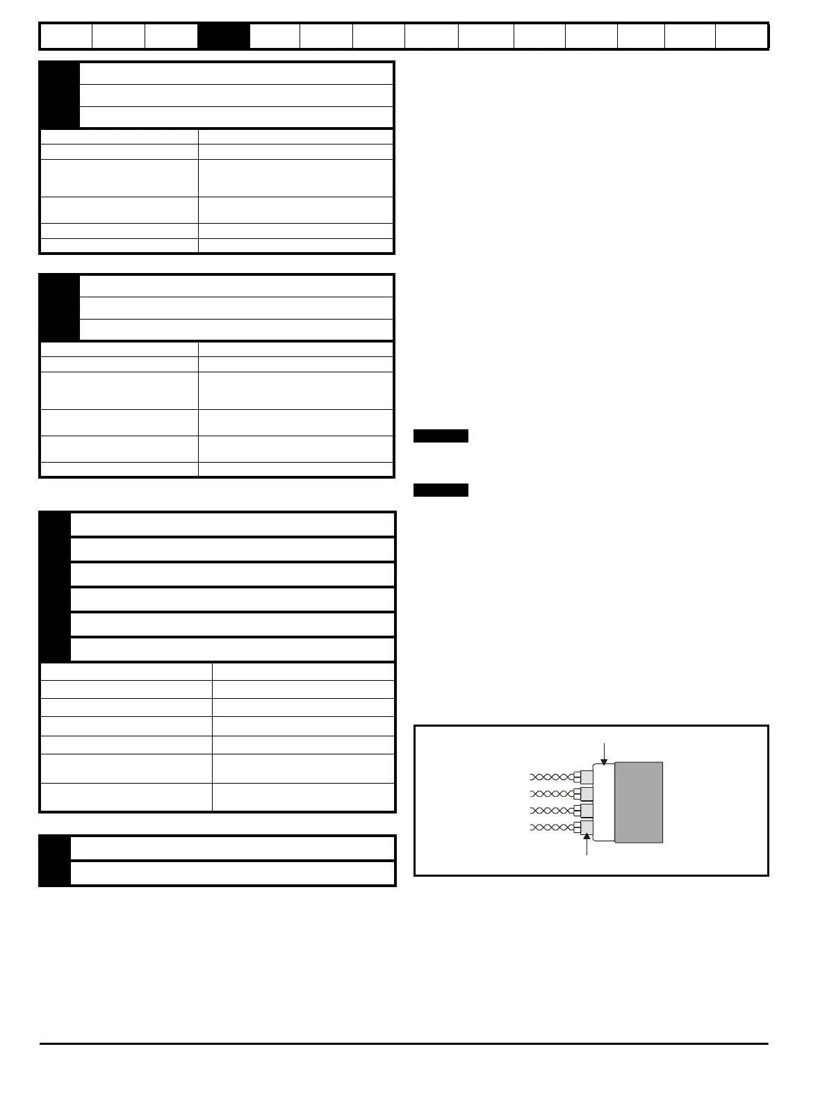
N
In order to guarantee maximum noise immunity for any application
double shielded cable as shown should be used.
In some cases single shielding of each pair of differential signals cables,
or a single overall shield with individual shield on the thermistor
connections is sufficient. In these cases all the shields should be
connected to ground and 0V at both ends.
If the 0V is required to be left floating a cable with individual shields and
an overall shield must be used.
Figure 4-21 and Figure 4-22 illustrate the preferred construction of cable
and the method of clamping. The outer sheath of the cable should be
stripped back enough to allow the clamp to be installed. The shield must
not be broken or opened at this point. The clamps should be installed
close to the drive or feedback device, with the ground connections made
to a ground plate or similar metallic ground surface.
Figure 4-21 Feedback cable, twisted pair
51 Relay 1 common
52 Relay 1 normally closed
53 Relay 1 normally open
Default function Drive OK indicator
Contact voltage rating 240Vac, installation over-voltage category II
Contact maximum current rating
5A AC 240V
5A DC 30V resistive load
0.5A DC 30V inductive load (L/R = 40ms)
Contact minimum recommended
rating
12V, 100mA
Default contact position Closed when power on and drive OK
Sampling period 4ms
61 Relay 2 common
62 Relay 2 normally closed
63 Relay 2 normally open
Default function Contactor enable
Contact voltage rating 240Vac, installation over-voltage category II
Contact maximum current rating
5A AC 240V
5A DC 30V resistive load
0.5A DC 30V inductive load (L/R = 40ms)
Contact minimum recommended
rating
12V, 100mA
Default contact position
Closed when AC or DC contactor is
required to be closed.
Sampling period 4ms
A Channel A, Frequency or Forward inputs
A\ Channel A\, Frequency\ or Forward\ inputs
B Channel B, Direction or Reverse inputs
B\ Channel B\, Direction\ or Reverse\ inputs
Z Marker pulse channel Z
Z\ Marker pulse channel Z\
Type EIA 485 differential receivers
Maximum input frequency 500kHz
Line loading <2 unit loads
Line termination components
100
Ω for 2 - 5V range (switchable)
Working common mode range +12V to –7V
Absolute maximum applied voltage
relative to 0V
±25V
Absolute maximum applied differential
voltage
±25V
+ + supply
0V 0V
Twisted
pair
cable
Twisted pair shield
Cable
Cable overall shield