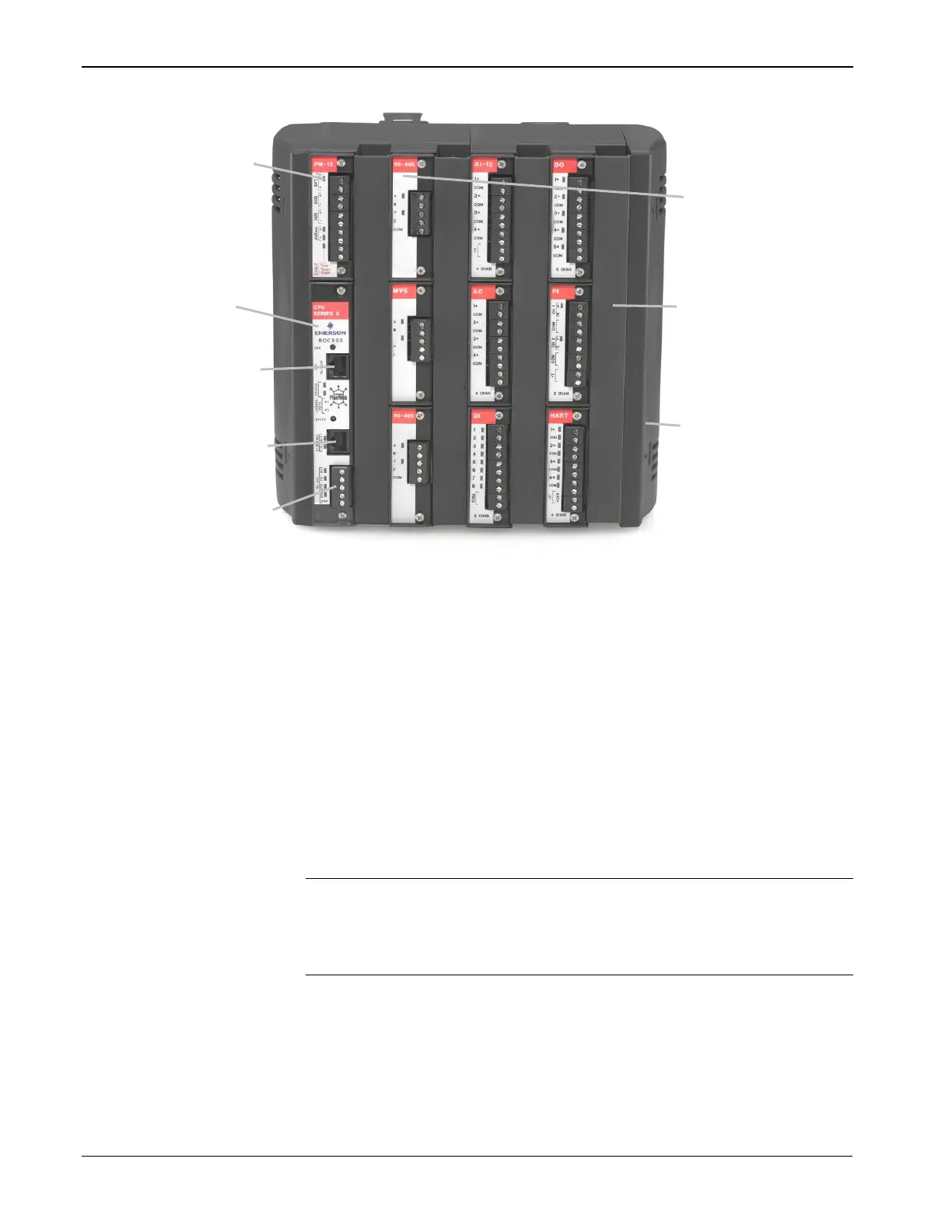
The left-most slots in the ROC809 (Figure 1-1) accommodate the
Power Input module and the CPU module. The remaining nine slots
can accommodate either communication modules or I/O modules (see
Table 1-1).
Note: If you use the optional communications modules, you can only
place those modules in the three slots (1, 2, or 3) immediately to
the right of the Power Input and CPU modules. Place I/O
modules in any available slot.
Figure 1-2 shows a ROC827 base unit (left) and a typical expansion
backplane (EXP) (right) populated with a full complement of six I/O
modules. Each EXP is composed of the same plastic housing as the
ROC827, contains six I/O slots, and has a powered backplane that easily
attaches to the ROC827 and other EXPs.