ROC800-Series Instruction Manual
3-28 Power Connections Revised July-2017
The ROC800 should have a minimum of bare wire exposed to prevent
short circuits. Allow some slack when making connections to prevent
strain.
3.5.1 Wiring the DC Power Input Module
Use 12 to 22 American Wire Gauge (AWG) wire for all power wiring.
It is important to use good wiring practice when sizing, routing, and
connecting power wiring. All wiring must conform to state, local, and
NEC codes. Verify that the hook-up polarity is correct.
To make DC power supply connections:
1. Install a surge protection device at the service disconnect.
2. Remove all other power sources from the ROC800.
3. Install a fuse at the input power source (see Figure 3-5).
4. Remove the terminal block connector from the socket.
5. Insert the bared end of each wire into the appropriate power module
connectors:
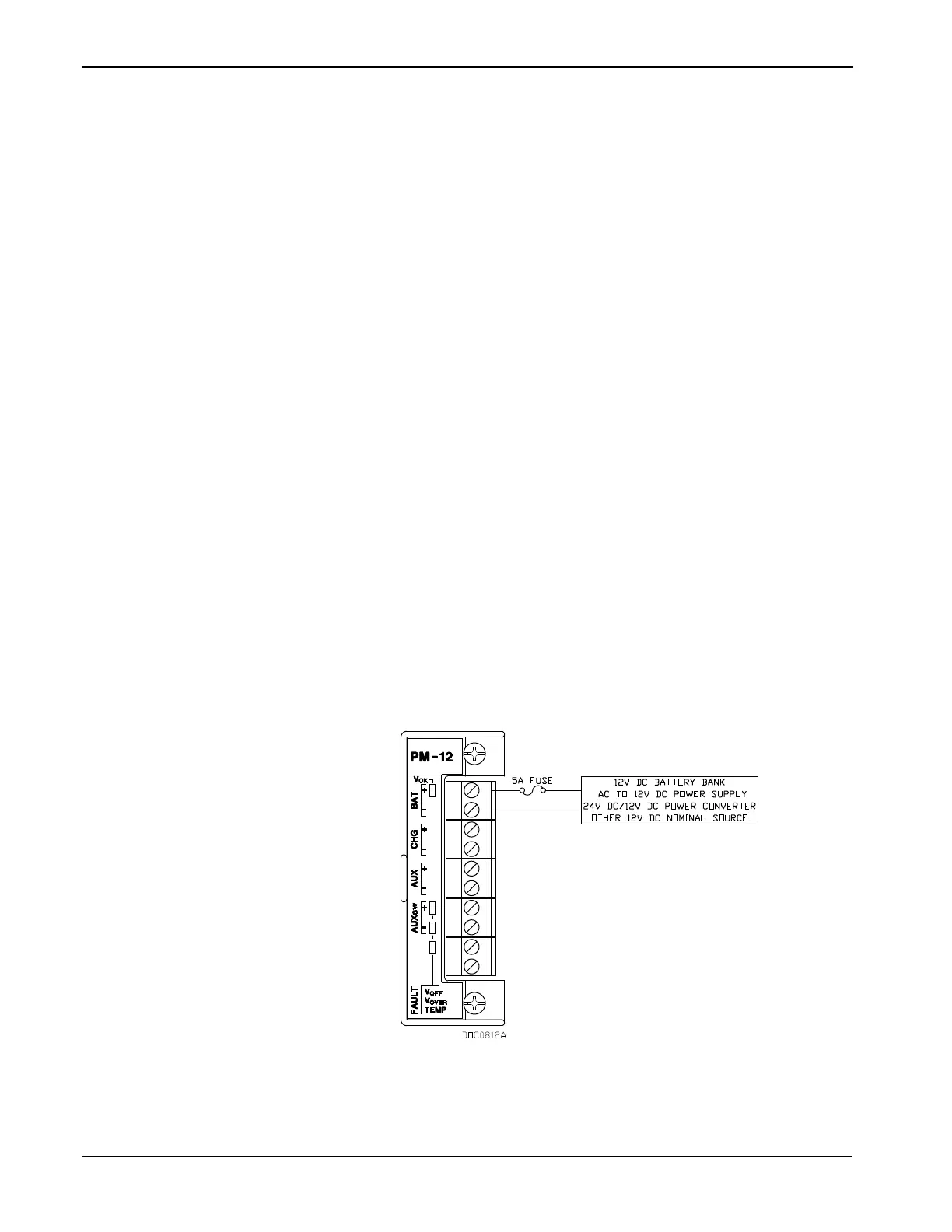
For PM-12 (12 Volts dc source): into the clamp beneath the
appropriate BAT+ and BAT– termination screws.
For PM-24 (24 Volts dc source): into the clamp beneath the
appropriate POWER INPUT+ and POWER INPUT– termination
screws.
For PM-30 (30 Volts dc source): into the clamp beneath the
appropriate POWER INPUT+ and POWER INPUT– termination
screws.
Figure 3-11. 12 Volts dc Power Supply and BAT+ / BAT- Wiring
6. Screw each wire into the terminal block.
7. Plug the terminal block connector back into the socket.