ROC800-Series Instruction Manual
5-2 Communications Revised July-2017
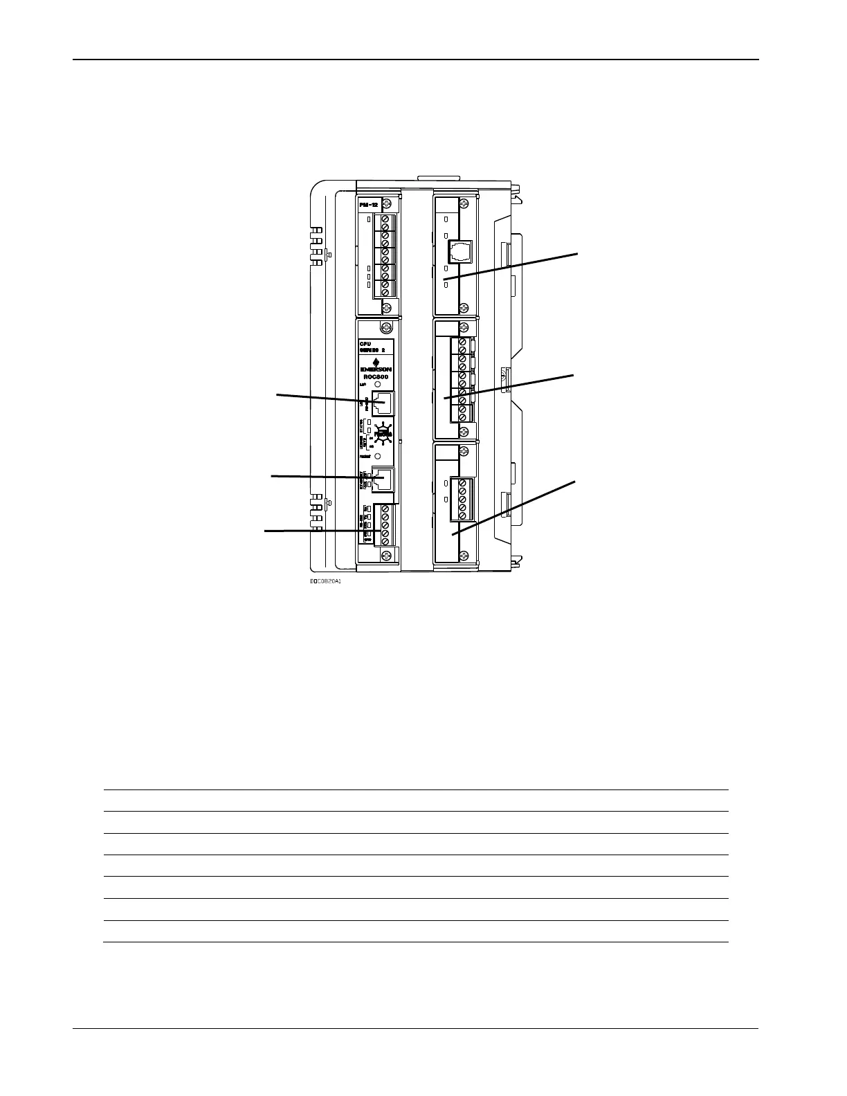
The communication modules consist of a printed circuit board, a
communication port, wiring terminal block, LEDs, and connectors to
the backplane. The ROC800 can hold up to three communication
modules in the first three module slots. Refer to Figure 5-1.
LOI (Local Port) EIA-232 (RS-232D)
Built-in Ethernet (Comm1)
Built-in EIA-232 (RS-232) (Comm2)
Optional Comm 3 (Slot #1)
Optional Comm 3 or Comm 4 (Slot #2)
Optional Comm 3 to Comm 5 (Slot #3)
Figure 5-1. Communication Ports
Table 5-2. RS-232 Communication LED Indicator Definitions
Clear To Send indicates the modem is ready to send.
Data Carrier Detect (DCD) indicates a valid carrier signal tone detected.
Data Set Ready for ring indicator communication signal.
Data Terminal Ready to answer an incoming call. When off, a connection disconnects.
Ready To Send indicates ready to transmit.
Receive Data (RD) signal is being received.
Transmit Data (TD) signal is being transmitted.
Each communication module has surge protection in accordance with
the CE certification EN 61000. With the exception of the EIA-232 (RS-