6. Apply power and set the loop to automatic control (if
applicable).
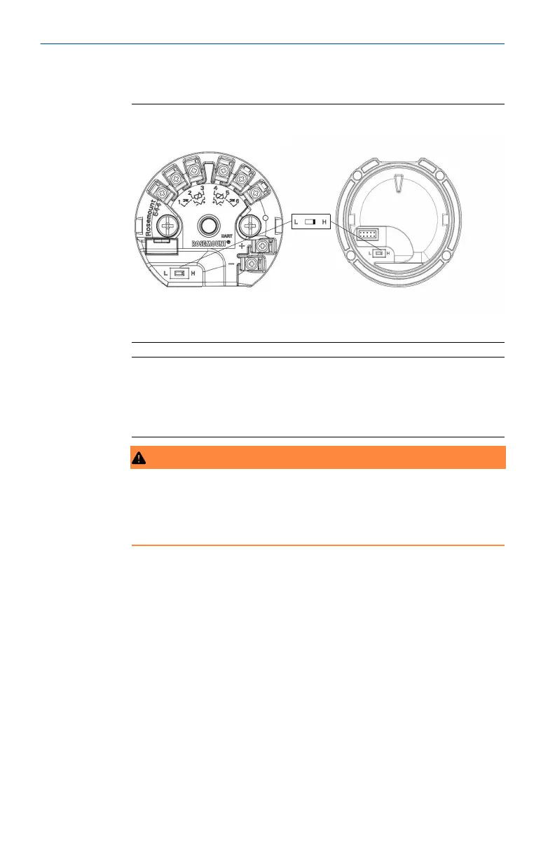
Figure 3-3: Alarm Switch Placement
A
Rosemount 644 Transmitter
Rosemount 644 Field Mount
A. Alarm switch
Note
If using an LCD display, remove the display by detaching it
from the top of the device, set the switch to the desired
position, reattach the LCD display, and reattach the housing
cover.
WARNING
Enclosure
Enclosure covers must be fully engaged to meet explosion-
proof requirements.
3.4 Verify configuration
Upon receiving your transmitter, verify its configuration using
any HART
®
-compliant configuration tool. See the Rosemount 644
Reference Manual for configuration instructions using AMS Device
Manager.
The transmitter communicates using the Field Communicator
(communication requires a loop resistance between 250 and 1100
ohms). Do not operate when power is below 12 Vdc at the transmitter
terminal. See the Field Communicator Reference Guide for more
information.
Quick Start Guide April2023
16 Rosemount 644