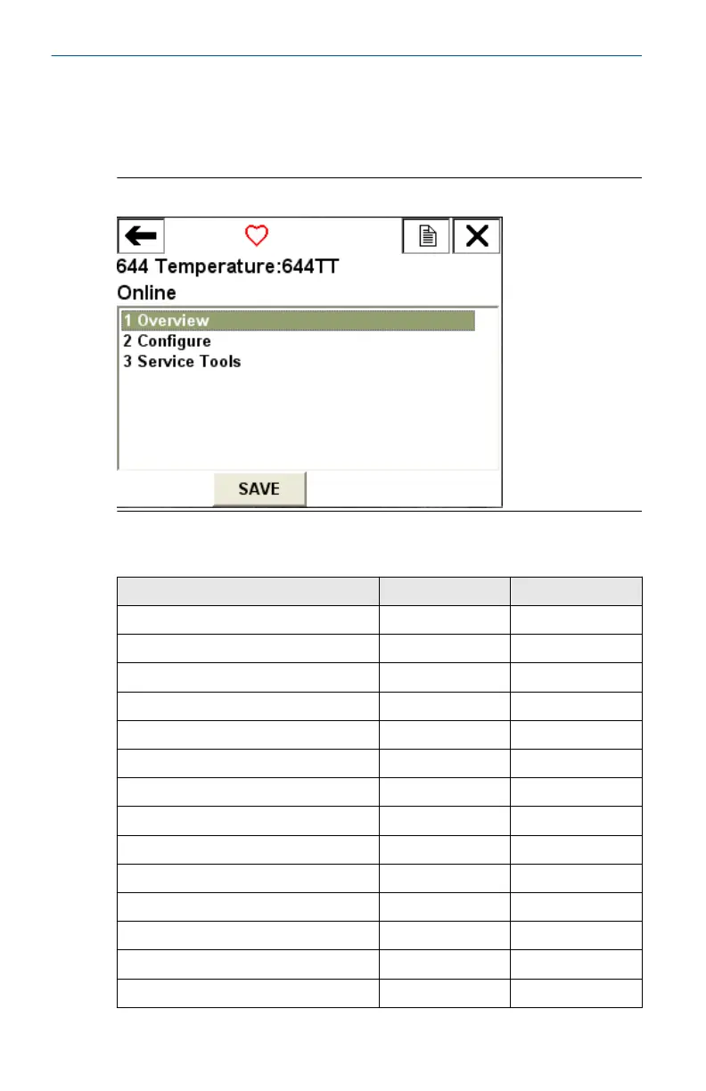
3.4.2 Field Communicator user interface
Two user interfaces are available to configure this device.
Figure 3-4 may be used for transmitter configuration and startup.
Figure 3-4: Device Dashboard Field Communicator Interface
Table 3-1: Device Revision 8 and 9 (HART
®
5 and 7), DD Revision 1
Fast Key Sequence
Function HART 5 HART 7
Alarm values 2, 2, 5, 6 2, 2, 5, 6
Analog calibration 3, 4, 5 3, 4, 5
Analog output 2, 2, 5, 1 2, 2, 5, 1
Average temperature setup 2, 2, 3, 3 2, 2, 3, 3
Burst mode 2, 2, 8, 4 2, 2, 8, 4
Comm status N/A 1, 2
Configure additional messages N/A 2, 2, 8, 4, 7
Configure Hot Backup
™
2, 2, 4, 1, 3 2, 2, 4, 1, 3
D/A trim 3, 4, 4, 1 3, 4, 4, 1
Damping values 2, 2, 1, 5 2, 2, 1, 6
Date 2, 2, 7, 1, 2 2, 2, 7, 1, 3
Display setup 2, 1, 4 2, 1, 4
Descriptor 2, 2, 7, 1, 4 2, 2, 7, 1, 5
Device information 1, 8, 1 1, 8, 1
Quick Start Guide April2023
18 Rosemount 644