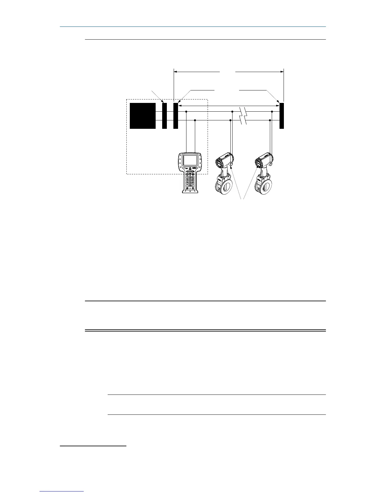
Figure 5-5: Flowmeter field wiring for Foundation fieldbus protocol
A
B
C
D
F
E
G G
H
A. 6234 ft (1900 m) max, depending upon cable characterisitcs
B. Integrated power conditioner and filter
C. Terminators
D. Fieldbus segment
E. Power supply
F. (Trunk)
G. (Spur)
H. Devices 1 through 16
(1)
Note
The power supply, filter, first terminator, and configuration tool are typically
located in the control room.
Procedure
1. Remove the housing cover on the side marked FIELD TERMINALS.
2. Connect the positive lead to the “+” terminal and the negative lead to
the “−” terminal as shown in Figure 5-3 for HART installations and
Figure 5-5 for Foundation fieldbus installations.
Note
Foundation fieldbus terminals are not polarity sensitive.
(1) Intrinsically safe installations may allow fewer devices per I.S. barrier.
October 2018 Quick Start Guide
Quick Start Guide 19

 Loading...