ER5000 —
67
Getting Started
Connect and verify the power supply (cont.)
WARNING
DO NOT open cover when an explosive atmosphere is present.
Doing so can result in property damage, serious injury or death.
Refer to Installing a Hazardous Location
Model (ER5050) on page 110 for more information.
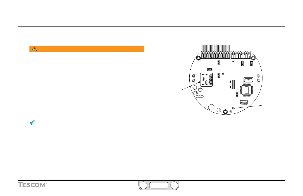
6. Unscrew and remove the cover of the ER5000 to view the
control board. Refer to Figure 10.
7. Check that the Power Indicator LED (LED1) is lit, which
indicates power is being supplied.
8. Check that the “Heartbeat” LED (LED4) blinks, which indicates
that the embedded controller software is running.
NOTENOTE
CAUTIONCAUTION
WARNINGWARNING
LED2 (green) and LED3 (amber) respond to data
transmission when the ER5000 communicates using RS485.
These LEDs do not respond to data transmission when the ER5000
communicates using USB and may be on or off depending on the
specic conguration of your application. They do not need to be
checked during installation or operation when USB is used.
9. Unplug the power supply.
LED4
“Heartbeat”
(red)
should blink
on and off at a
steady rate
LED1
Power Indicator
(red)
should be on
continuously
Figure 10: These LEDs Indicate That the ER5000 Has Been
Successfully Connected to the Power Supply