ER5000 —
80
Installation Variations
Voltage/Current Select Jumpers
WARNING
The controller must be disconnected from the power supply before
any additional wiring or change to jumper configuration is
performed. Do not reconnect the power supply until all additional
wiring connections have been made and are properly installed.
NOTENOTE
CAUTIONCAUTION
WARNINGWARNING
If you are replacing an ER3000 in an existing application and
wish to continue using your current software such as the Windows Tune
program, you will need to install Jumper J9. The default conguration
for Jumper J9 is NOT installed.
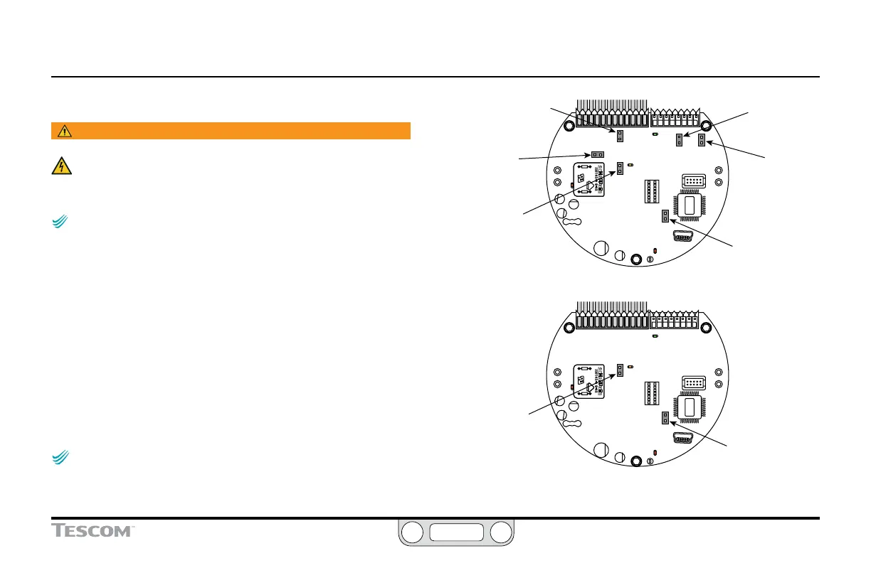
Figure 19 shows the voltage/current select jumpers on
the ER5000.
Jumpers J5, J6, J14 and J15 are used to select between 4–20 mA
and 1–5V sources for setpoint, external feedback, auxiliary
input #1 and auxiliary input #2 respectively. For these jumpers,
having the jumper installed (ON) congures the controller
for 4–20 mA input and having the jumper not installed (OFF)
congures the controller for 1–5V input.
NOTENOTE
CAUTIONCAUTION
WARNINGWARNING
0–10V models of the ER5000 do not have these jumpers.
(continued next page)
Figure 19: Jumpers
Jumper J5
Setpoint
ON = 4–20 mA
OFF = 1–5V
Jumper J1
Ground Filter
Bypass
ON = Signal ground
connected to power
ground
OFF = Normal mode,
no connection
(recommended)
Jumper J1
Ground Filter
Bypass
ON = Signal ground
connected to power ground
OFF = Normal mode, no
connection (recommended)
Jumper J6
External Feedback
ON = 4–20 mA
OFF = 1–5V
4–20 mA / 1–5V Models
0–10V Models
Jumper J14
Auxiliary Input #1
ON = 4–20 mA
OFF = 1–5V
Jumper J15
Auxiliary Input #2
ON = 4–20 mA
OFF = 1–5V
Jumper J9
ER3000 / ER5000
Mode Select
ON = ER3000
OFF = ER5000
Jumper J9
ER3000 / ER5000
Mode Select
ON = ER3000
OFF = ER5000