Electronic Bypass Controller Installation and Commissioning Guide 13
2.5.5.4 Internal Control Wire Connections
There are factory connections between the electronic bypass control board and the
H300 inverter. These connections are made at the factory and are for reference only. DO
NOT change this wiring as it will cause the electronic bypass to operate improperly or
not at all.
Electronic Bypass
Control Board H300
Unidrive
M200/M400 Wire Number
J11 – 1 Motor overload relay Motor overload relay 12
J11 – 2 22 10/10 11
J11 – 3 28 1/6 16
J11 – 4 27 14/14 10
J11 – 5 N/C N/C N/A
J11 – 6 24 12/12 8
J11 – 7 23 13/11 9
J10 - 1 Input Contactor 5 5
J10 – 2 Bypass Contactor 4 4
J10 - 3 Output Contactor 3 3
J10 - 4 115 Vac (Neutral) 2 2
J10 - 5 115 Vac (Hot) 1 1
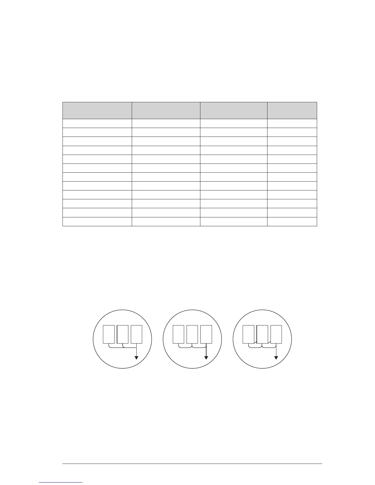
2.5.6 Grounding
Never ground the electronic bypass package in common with welding machines,
motors or other high current electrical equipment. Run all ground wires in a separate
conduit.
When using several electronic bypass packages side by side, ground as shown below.

 Loading...


