3 – 2
Section 3 • Installation
VSS/VSR/VSM/VSH/VSSH Compressor • Installation, Operation and Service Manual • Emerson • 35391S
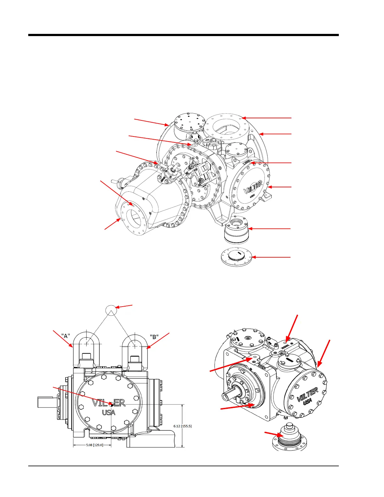
Main Lift Point
Center of
Gravity
Lifting Eye
Lifting Eye
Lifting Point A
1/2-13 UNC
Lifting Point B
1/2-13 UNC
ROLLER BEARING
HOUSING
GATEROTOR BALL
BEARING SUPPORT
GATEROTOR
COVER
Figure 3-2. Bareshaft Compressor Assembly Center of Gravity (Models 97-127)
To lift the compressor, use lifting points on compres-
sor frame to attach the lifting device, see Table 3-2 and
Figure 3-1 to 3-6. There are a few points to consider prior
to moving it:
• Ensure that the weight is evenly distributed amongst
the lifting device (i.e. lifting chains and spreader bar)
prior to lifting.
• Ensure that the lifting device is not obstructed by
any parts of the compressor to prevent damage to
components.
• Use additional personnel as needed to spot and aid in
maneuvering the compressor.
• Ensure there is plenty of space to maneuver the com-
pressor, and a clear path to its location.
Figure 3-1. Bareshaft Compressor Lifting Points and Component Weights
E
E
D
C
B
A
Discharge
Manifold
Main Compressor
Assembly
Gaterotor
Cover
Gaterotor
Bearing Housing
Cover
Gaterotor
Bearing Housing
Model 1551-2101 Shown
MAIN HOUSING LIFTING
POINT 1/2-13 UNC

 Loading...


