5 – 14
Section 5 • Maintenance/Service
VSS/VSR/VSM/VSH/VSSH Compressor • Installation, Operation and Service Manual • Emerson • 35391S
Main Rotor Bearing Radial Clearance Inspection
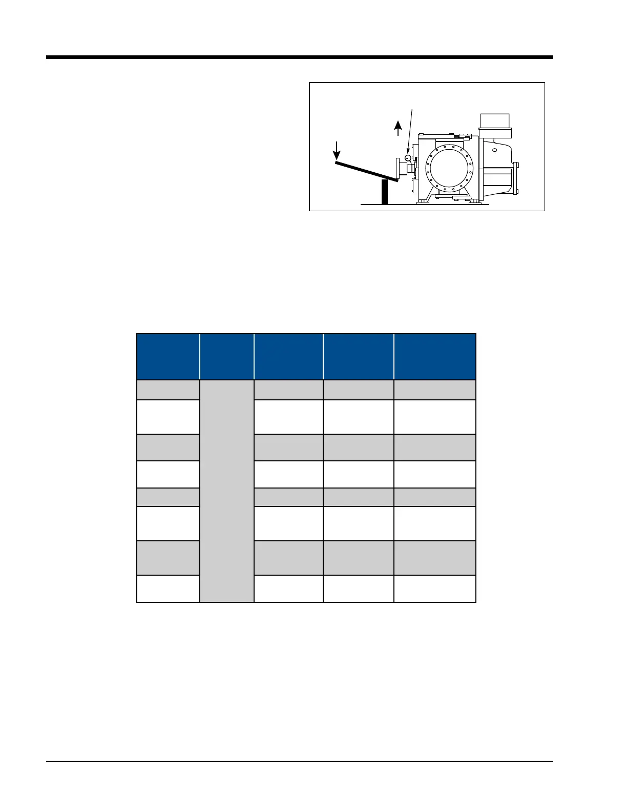
6. Install dial indicator to the compressor frame and
zero indicator, see Figure 5-9.
NOTE
Do not exceed maximum applied force. For
maximum applied forces of all compressor models,
see Table 5-3.
7. Place lever arm and fulcrum underneath hub and
push hub upwards. Record measurement.
8. If measurement is out of allowable tolerance shown
in Table 5-3, the bearing may need to be replaced.
Contact Vilter
TM
Technical Support.
Side View
Rigidly attach dial indicator.
Direction of shaft
movement.
Applied Force
Shaft being pushed by use of lever.
Figure 5-9. Bearing Radial Clearance
Inspection
Compressor
Model
Max. Axial
Clearance
in. (mm)
Max. Radial
Clearance
in. (mm)
Max. Force at
Hub/Shaft
lbf (N)
Max. Applied
Force
(36” Lever, 6” Pivot)
lbf (N)
97-127
0.002
(0.051)
0.004 (0.102) 100 (444) 20 (89)
151, 181, 201,
152, 182, 202,
301, 361, 401
0.006
(0.152)
100
(444)
20
(89)
501, 601, 701
0.007
(0.178)
150
(667)
30
(133)
291, 341, 451,
601
0.007
(0.178)
150
(667)
30
(133)
751, 901
0.006 (0.152) 200 (890) 40 (178)
791, 891,
1051, 1201,
1301
0.006
(0.152)
300
(1335)
60
(267)
1501, 1551,
1801, 1851,
2101
0.007
(0.178)
400
(1780)
80
(356)
2401, 2601,
2801, 3001
0.006
(0.152)
600
(2670)
120
(534)
Table 5-3. Maximum Main Rotor Bearing Clearance

 Loading...


