3 – 8
Section 3 • Installation
VSS/VSR/VSM/VSH/VSSH Compressor • Installation, Operation and Service Manual • Emerson • 35391S
Stop/Check Valve Installation
1
The new design will apply only to the 2” thru 4” stop
valves. Retrotting a eld installation will require replac-
ing the bonnet assembly.
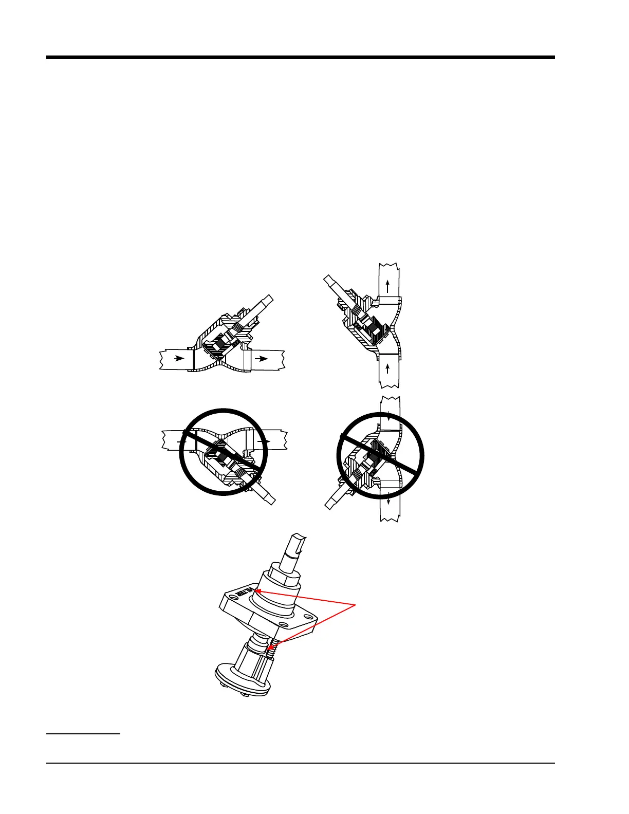
The bonnet must be installed with the spring towards
the bottom, see Figure 3-7. The drill xture is designed
so that the hole for the spring will always be drilled on
the opposite side from the cast-in Vilter name on the
bonnet. From the outside of the valve, the casting num-
bers must always be towards the top of the valve.
For Stop/Check Valve Operation, refer to Section 4.
1 For VSM-97, VSM-113 and VSM-127 this is just a
Stop Valve
Correct
Wrong
Wrong
Correct
Figure 3-7. Stop/Check Valve Orientation
Verify the location
of the Spring and
note the Vilter
TM
name.

 Loading...


