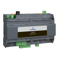
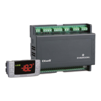
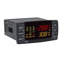
(*)= 12Vdc - 250mA. Compatible modem TC35-KIT (MC55i by Siemens, CINTERION L30960N2700A100),
Gatetel GT-HE910-EUD, Gatetel GT-HE910-NAD
(**)= For XWEB 500DIN only
NOTE: The status of the System LED depends on that of the relative "System alarm" relay.
NOTE: for XWEB300D, the AUX 'system relay' assumes the following logic:
at rest (XWEB off) contacts 7 and 9 are closed
in the event of an alarm, it closes at 7-8
at start-up, it closes at 7-8 for a few seconds and, if there are no alarms, it returns to rest and closes
at 7-9.
NOTE: The state of the LEDs ALARM 1 and 2 correspond to the state of ALARM CONTACTS 1 and 2 the
following logic:
1. illuminated LEDs to shorted contacts
2. Led off to open contacts
In case of absent power, the contacts are normally open.
In the event of a powered system, the contacts are open or closed depending on the software configuration
together with the alarm state.
NOTE: always use the power supply of the external modem of the same XWEB to guarantee the correct
transmission of messages (e.g. SMS messages). Use the cord provided with KIT at terminals 10-11.

 Loading...

