Grip Frame and Bolt Guide Locking Assembly
Warning: It is recommended that you do not remove the grip frame, as removing it
will expose the bolt guide locking assembly; this consists of a spring, detent, and but-
ton. These parts are held in place by the grip frame. If you do need to remove the grip
frame, be careful not to lose these parts.
Removal of Grip Frame
• Using a 1/8” Allen wrench, remove both grip frame retention screws turning
by them counter-clockwise.
• Gently pull the frame up from the body. When pulling the frame off the body,
make sure not to lose the bolt guide locking components.
Bolt Guide Locking Assembly
• Before you re-installing the grip frame make sure the bolt guide locking detent is
within the housing; see Fig. 15.1.
• Applying grease to the bolt guide locking detent will help keep it in place.
• Once you have conrmed all of the bolt guide locking parts are in place, you
can install the grip frame.
Installation of Grip Frame
• Inspect the male air transfer tube bottom O-ring and lightly grease.
• Make sure the bolt guide locking spring and button are in place within the frame
and that the bolt guide locking detent is within the air transfer plate.
• As you install the grip frame, make sure the solenoid wires do not get pinched.
• Gently push grip frame back on and line up the air transfer tubes.
• When frame is back on, use the 1/8” Allen wrench and tighten the (2) grip frame
retention screws clockwise.
Removal, Installation, and Cleaning of Ball Detents
• Using a 5/64” Allen wrench, insert Allen wrench into detent cover and turn
counter-clockwise.
• Clean the detents with a damp cloth and apply a small amount of grease to
the outer sides of the detents if sticking is an issue.
• Installation is the reverse of the removal. Do not over tighten the ball detent covers!
Note: Be careful not to lose any of the detent parts as they are small.
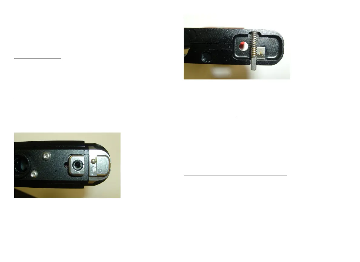
• Next check that the bolt guide locking button and spring are located correctly
within the grip frame; see Fig. 15.2.
(Fig. 15.1)
(Fig. 15.2)