©2021 EMS Ltd. All rights reserved. Page 8 of 28 TSD113-0001-99 (Issue 3) 19/05/2021 AJM
ZONES IN FIRE 01
01: Ground Floor
View>
Fire Control Panel
System Normal
12:12 Access
Fire Control Panel
System Normal
11/01/20 Access
FIRE ZONES
FIRE
INFORMATION ZONES
ALERT
FIRE ZONES
FIRE
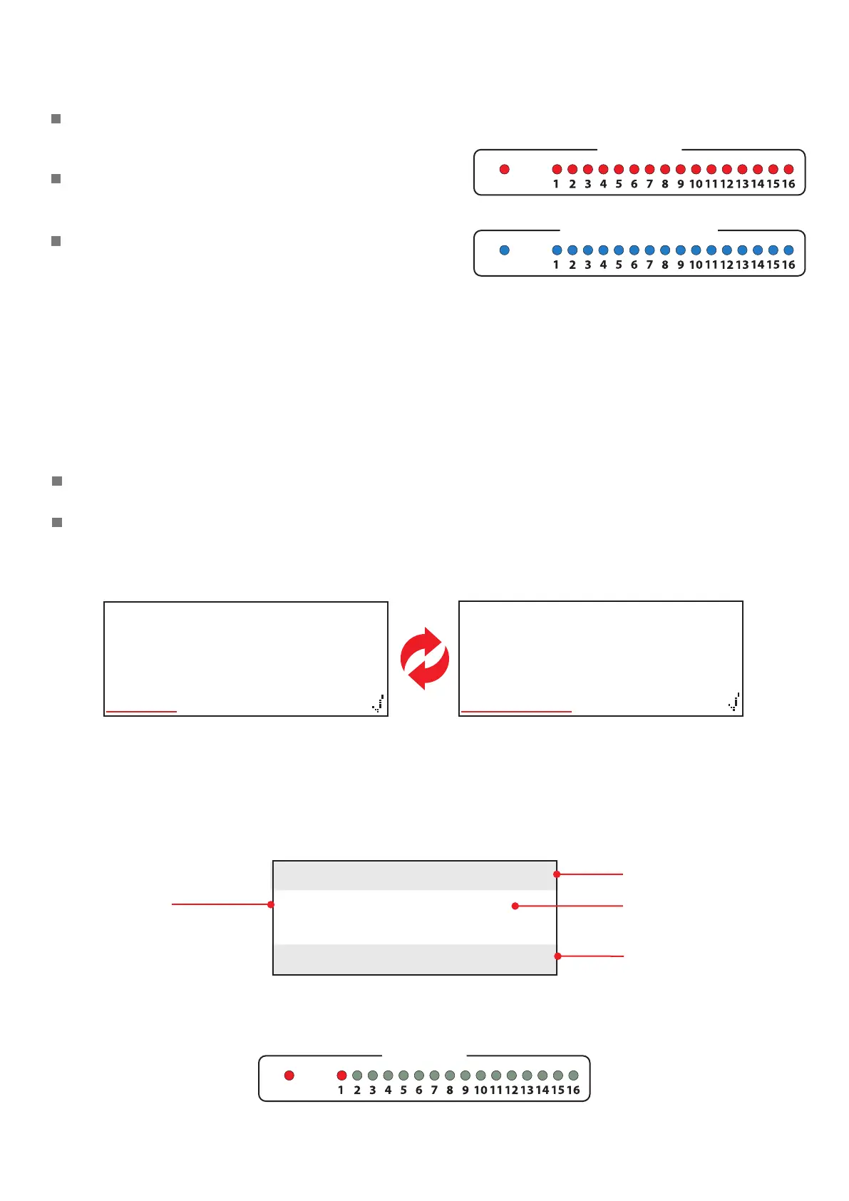
Zone LED indication
Fire devices and Information devices have separate
zonal LED Indication.
Fire devices have associated RED fire zone LEDs as
shown.
Information devices have associated BLUE
information zone LEDs.
Fire control panel display
Whilst the SmartCell control panel is fault free, it’s display will state ‘System Normal’.
The time and date will alternate in the bottom le hand corner.
An example is shown below:
Normal display
Fire event display
An example fire event display is shown below.
1
st
zone in alarm
Number of zones in fire
Zone’s text description
(Up to 16 characters)
Option to view details
The general red “Fire” LED and the individual zone’s red “Fire” LED will both be illuminate as shown.
The SmartCell control panel’s buzzer will also sound.
Note: LEDs will only illuminate upon re and alert events.