EM TEST CNV 504N1/N2 / 508N1/N2
Operating manual V 1.20 18 / 23
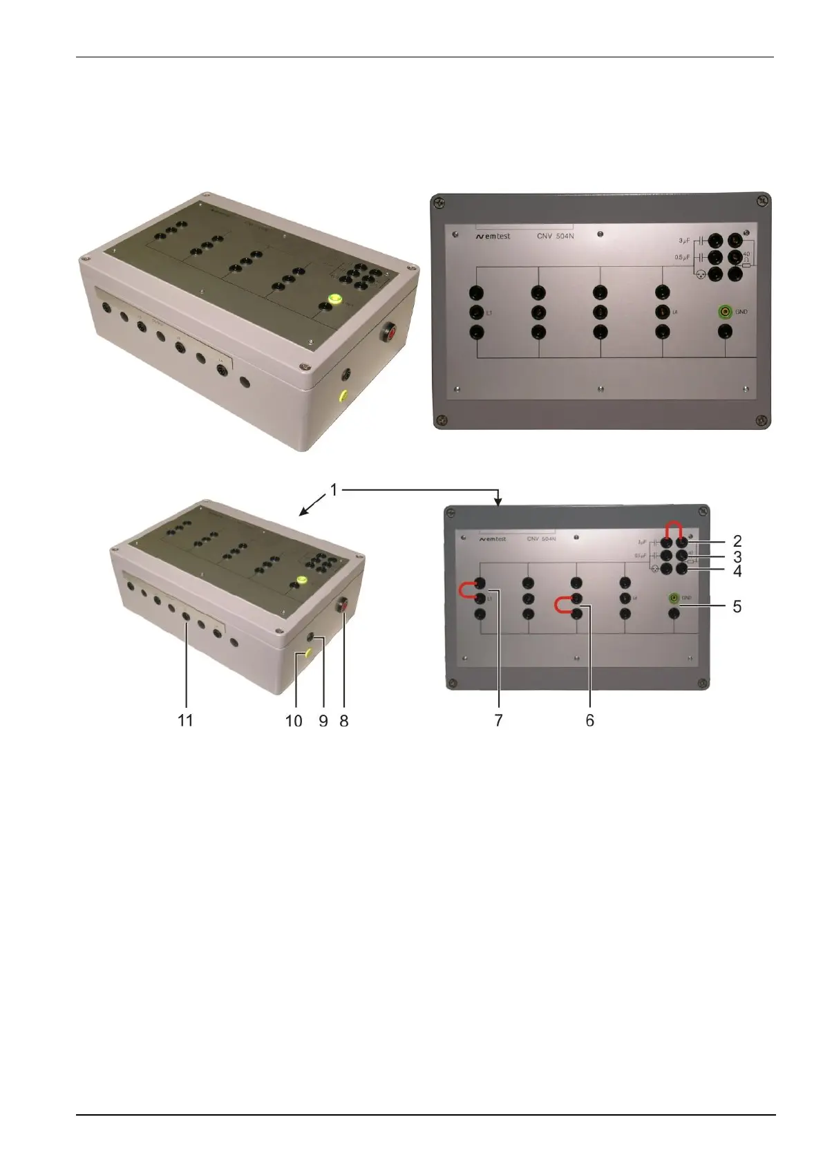
Coupling network CNV 504N1, CNV 504N1.2, CNV 504N1.3, CNV 504N1.6
1. Input data lines
2. Coupling ringwave
3. Coupling with 0.5F / 40
4. Coupling with gas arrestor / 40
5. Connection PE / COM
6. Coupling data lines - COM ( L3- COM)
7. Coupling data lines - HV (HV - L1)
8. HV-IN connector surge 1.2/50
9. COM connector Surge 1.2/50
10. PE connector
11. Output data lines to EUT
Remark:
CNV504N1.2 and CNV504N1.3 have the same design. The gas arrestor is not mounted in these devices.