EM TEST CNV 504N1/N2 / 508N1/N2
Operating manual V 1.20 22 / 23
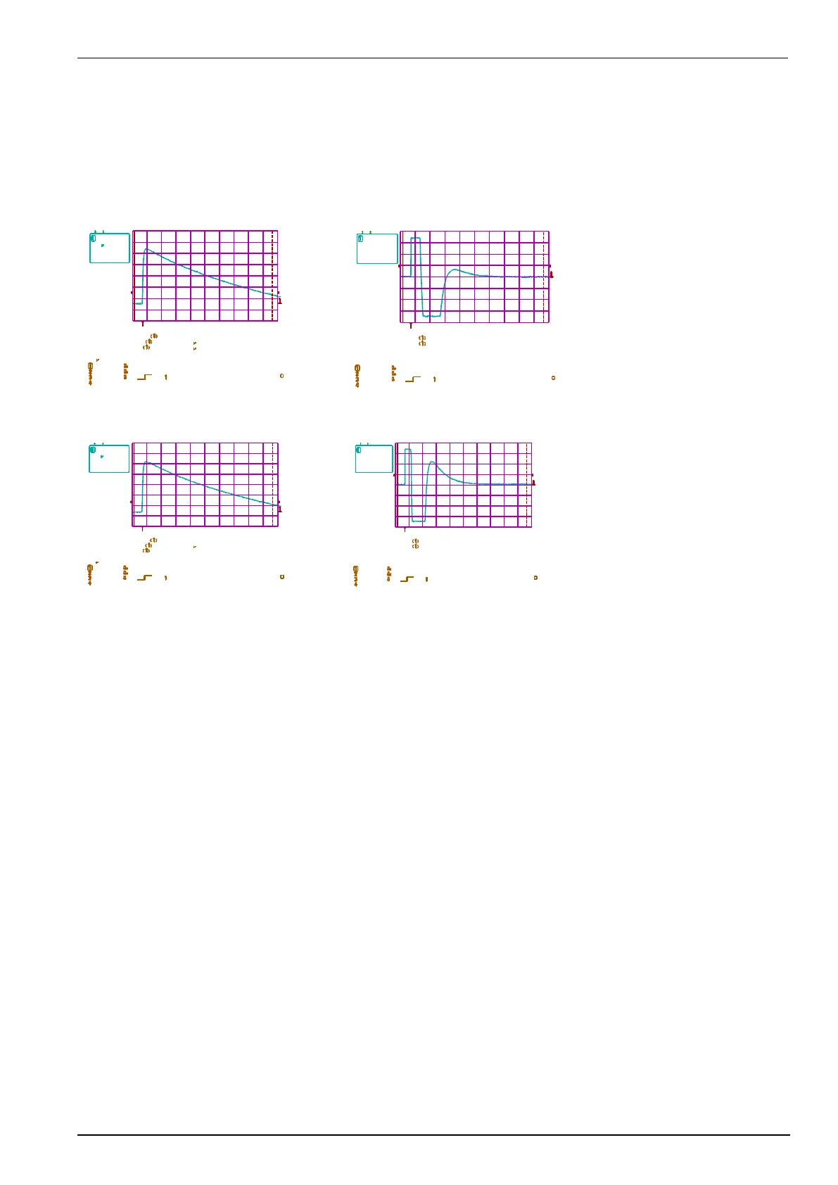
Overvoltage protection on sensor input
The diagrams shown in this section are the ones being valid for the standard coupling/decoupling network rated
50V/1A. The values for the voltage limitations as shown in figures 2 and 4 will differ according to the specified
operation voltage.
The following part shows the diagrams with impulses with different couplings
2 0 - J u l- 9 4
103120
1 0 s
2 0 0 V
D C 0 . 1 8 8 k V
10 s
2 V
2 . 7 0 V
. 5 V
. 1 V
DC
DC
DC
DC
N O R M A L
1 0 0 M s / s
m a x im u m
9 6 9 V
w id t h
4 2 . 0 0 5
s
r is e
1 . 0 0 1 s
2 0 - J u l- 9 4
103237
. 5 m s
2 0 . 0 V
D C 1 8 . 8 V
. 5 m s
. 2 V
2 . 7 0 V
. 5 V
. 1 V
DC
DC
DC
DC
N O R M A L
2 M s / s
m a x im u m
6 9 . 4 V
m in im u m
- 7 0 . 0 V
Fig 1: pulse 1,2/50 s, symmetrical coupling; line to line
Fig 2: pulse 1,2/50 s, symmetrical coupling; residual voltage at the input.
2 0 - J u l- 9 4
103351
1 0 s
2 0 0 V
D C 0 . 1 8 8 k V
10 s
2 V
2 . 7 0 V
. 5 V
. 1 V
DC
DC
DC
DC
N O R M A L
1 0 0 M s / s
m a x im u m
9 6 8 V
w id t h
4 2 . 3 4 9
s
r is e
9 8 7 n s
2 0 - J u l- 9 4
103449
. 5 m s
2 0 . 0 V
D C 1 8 . 8 V
. 5 m s
. 2 V
2 . 7 0 V
. 5 V
. 1 V
DC
DC
DC
DC
N O R M A L
2 M s / s
m a x im u m
6 9 . 4 V
m in im u m
- 7 0 . 0 V
Fig 3: pulse 1,2/50 s, unsymmetrical coupling; line to earth
Fig 4: pulse 1,2/50 s, unsymmetrical coupling; residual voltage at the input.
Spec devices: The residual voltage is according the ordered specification in the technical data.