EM TEST CNV 504N1/N2 / 508N1/N2
Operating manual V 1.20 9 / 23
Device functions and operating
Operation elements on the CNV 504 / CNV 508 series
The position of the short circuit connectors are in relation to standard IEC 61000-4-5 as figure 11 and 12 respec-
tive figure 9 in IEC 61000-4-12 for Ringwave.
The switches S1 and S2 correspond to the positions of the jump-
ers on the pictures.
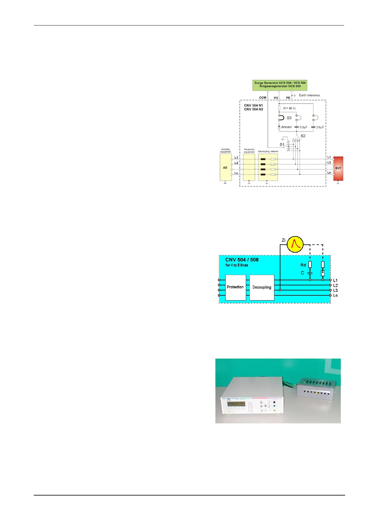
With two short-circuit connectors (S1 …S3) the coupling modes
can be selected on top/front of the coupling unit.
S1: Return of a line or the earth back to the generator COM
S2: Coupling of the high voltage to one line
S3: Selection of the coupling mode via gas arrestor or 0.5F
coupling capacitor or the 3.0F capacitor for ringwave
pulse.
It is not possible to couple several lines at the same time. The
operator would cause a short-circuit between the lines.
The operator has to select „/“ for the coupling mode of the surge
generator. This means that no coupling mode for the internal cou-
pling network of the surge generator shall be selected.
General
The coupling network has to couple the interference pulses in a well defined way to the input/output lines of an
electronically system. The coupling is realized by coupling capacitors according IEC 61000-4-5 in figure 11 or with
the help of gas arrestors as per IEC 61000-4-5, figure.
The decoupling part is required for the following reasons:
to decouple auxiliary equipment or other instruments connected
at the same line; protection of non tested equipment
to increase the line impedance for the surge generator
Due to the filter of the CNV decoupling network the data signals
cannot pass the CNV. CDN with special decoupling networks can
extend the frequency range.
Input / output to CNV 504 / 50x
The input/output connectors of the coupling network are located at each side of the housing. The lines under test can
be connected with safety laboratory cables. All lines are single lines.
Also at one side of the housing the connectors for the surge
generator are mounted. There are the same cables as be used for
the CNV 503 or the coupling matrix CNI for coupling to power
lines.
For reduce the influence of the cable we propose to twist the
high voltage cables from the impulse generator to the CNV
The plugs have the following color code:
High voltage HV : coaxial cable or red cable ( >4kV)
High voltage COM : black
Earth connection CNV : green - yellow
The earth must be connected at the earth plug on the rear side of the generator UCS500 / VCS500.