EM TEST CNV 504N1/N2 / 508N1/N2
Operating manual V 1.20 11 / 23
Test setup
According to the standard IEC 61000-4-5 the coupling impedance to signal- and data lines is 42.
The impedance is separated in 2 built in the impulse generator and 40 in the CNV 504 network.
Arrangement
Both equipment, the surge generator and the coupling
network can be mounted above or besides each other,
whatever is more convenient.
The equipment must be connected by the following cables:
High voltage cable, coaxial type.
high voltage common cable (black safety laboratory cable)
Earth cable
For generators with more than 4kV the high voltage cables
are designed with banana plugs.
For reduce the influence to the waveshape we propose to
drill the HV and COM cables.
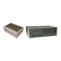
Using the CNI 503 output to the CNV
For earthing the CNV 50x do not use the earth connector of the EUT output on the front panel. This Earth is in-
tern decoupled for burst testing.
Grounding
According IEC 61000-4-5 the decoupling part is specified so that an increased ground current is caused.
This means:
1. Ground fault current relays cannot be used in laboratories in which surge testing is daily practice.
2. Both equipment, the generator and the coupling/decoupling network, therefore must be well connected to
the protective earth system of the test setup.
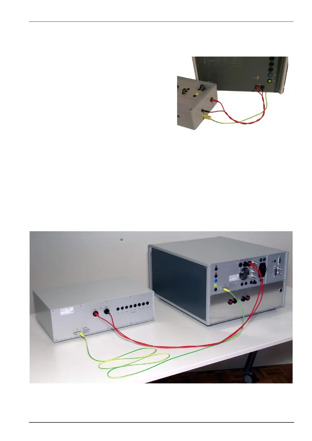
Test setup with CNV 504N2
Example of a test setup with UCS 500N7 and CNV 504N2. The Ground must be connected to the Groundplane, if
there is one, and to the building GND