25
A.Confirm that the distance between the bottom of the coupling and the motor is 5 mm;
B.Insert the screw rod into the coupling, confirm the screw reach the bottom, and lock the screw with tools;
C.Fix the motor and screw to the back of the left profile of the Z-axis with two M4x18 hexagon socket
countersunk head screws.
Note: To lock the ship-type nut, it must be perpendicular to the profile slot.
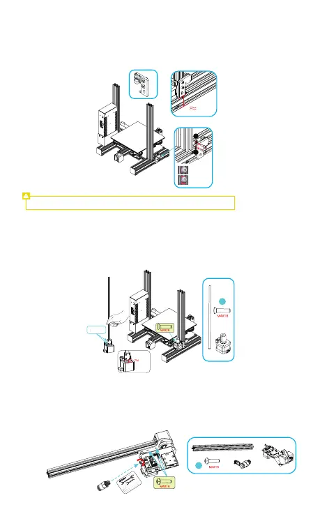
Install the Z-axis limit switch
Secure the Z-axis limit switch to the outside of the left profile of the Z-axis with 2 x M5*8 hexagon socket
button head screws and 2 ship-type nuts at a distance of 32 mm from the lowest part of the bottom
profile.
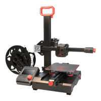
Install the extrusion kit
A.Lock and secure the extrusion kit to the X-axis profile with two M4X16 hexagonal button head spring
washer combination screws;
B.Then fix the pneumatic coupling to the extrusion kit with an open-end spanner, and tighten it in the
direction shown in the figure.
Install the Z-axis motor and screw rod
a
b
a:Fasten it
b:Then
embed it
Auto leveling, no installation needed
5mm
26
32mm