Parameter description (FF configuration program) Cerabar S/Deltabar S/Deltapilot S FOUNDATION Fieldbus
38 Endress+Hauser
7 Parameter description
(FF configuration program)
In this chapter the parameter text as well as the parameter name are indicated. In FF configuration
programs only the parameter text is displayed (exeption: in the NI-FBUS configurator you can select
if the parameter text or the parameter name is displayed).
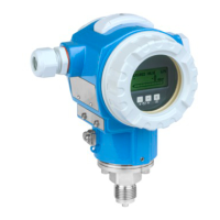
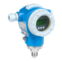
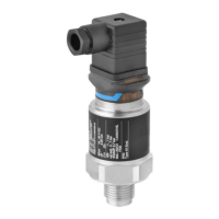
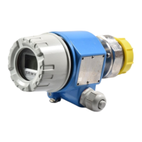
P01-xxxxxxxx-07-xx-xx-en-001
!
Note!
• With FOUNDATION Fieldbus, all the device parameters are categorized according to their
functional properties and task and are assigned to the Resource Block, the Transducer Blocks and
the function blocks. The parameters of the Resource Block, the Transducer Blocks and the Analog
Input Block are described in this section. For a parameter description of the other function blocks,
such as the PID or Discret Ouput Block, see Operating Instructions BA00013S "FOUNDATION
Fieldbus Overview" or the FOUNDATION Fieldbus Specification.
• Some parameters are only relevant if other parameters are appropriately configured. For example,
the Customer Unit P/CUSTOMER_UNIT_PRESSURE parameter is only relevant if the "User
unit" option was selected beforehand via the Calibration Units/CAL_UNIT parameter. There is a
comment in the parameter description here stating: Note: prerequisite: Calibration Units/
CAL_UNIT = User unit.
• The menu path is indicated in the header of each table. You can use this path to get to the
parameters in question.
• The menu has a different structure depending on the measuring mode selected. This means that
some function groups are only displayed for one measuring mode, e.g. the "LINEARIZATION"
function group for the "Level" measuring mode. If certain requirements have to be met for a
function group, these are listed in the first row of the table.
• In the "Parameter name" column, the unique identification number (ID) of the parameter is
indicated in brackets. This ID only appears on the local operation.
7.1 Cerabar S/Deltabar S/Deltapilot S block model
The Cerabar S/Deltabar S/Deltapilot S has the following blocks:
• Resource Block (device block)
•Transducer Blocks
– Pressure Transducer Block
This Block supplies the output variables Primary Value/PRIMARY_VALUE and Secondary
Value/SECONDARY_VALUE. It contains all the parameters to configure the measuring device
for the measuring task such as measuring mode selection, linearization function and unit
selection.
– Service Transducer Block
This Block supplies the output variables Counter: P > Pmax/COUNTER_PMAX, Max. Meas.
Press./MAX_MEASURED_PRESSURE and Pressure/PRESSURE. It also includes all the
counters for measuring range overshoot/undershoot for pressure and temperature, minimum
and maximum measured values for pressure and temperature and the HistoROM function.
– DP Flow Transducer Block (only Deltabar S)
This Block supplies the output variable Totalizer 1/TOTALIZER_1_VALUE and Totalizer 2/
TOTALIZER_2_VALUE. It contains all the parameters that are needed to configure this
totalizer.
– Diagnostic Transducer Block
This Block does not return any alarm messages. It contains the simulation function for the
Pressure Transducer Block, parameters to configure the alarm response and the user limits for
pressure and temperature.
Parametertext Parametername
Linearization/LINEARIZATION