Do you have a question about the Endress+Hauser Cerabar M PMC51? Cerabar M PMP51 and is the answer not in the manual?
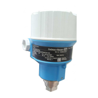
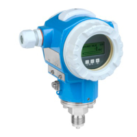
| Type | Cerabar M PMC51 / PMP51 |
|---|---|
| Measuring Principle | Piezoresistive |
| Measured Variable | Pressure |
| Output Signal | 4...20 mA HART, PROFIBUS PA, Foundation Fieldbus |
| Power Supply | 10.5 to 45 V DC (HART), 9 to 32 V DC (PROFIBUS PA, FOUNDATION Fieldbus) |
| Process Temperature | -40 to +85 °C (-40 to +185 °F) |
| Ambient Temperature | -40 to +85 °C (-40 to +185 °F) |
| Housing Material | Aluminum, stainless steel |
| Diaphragm Material | Stainless steel |
| Process Connection | Threaded, flanged, sanitary |
| Protection Class | IP66 |
| Material | Diaphragm: 316L |
| Approvals | ATEX, IECEx, SIL, FM, CSA |
| Communication | HART, PROFIBUS PA, Foundation Fieldbus |
Outlines responsibilities and prerequisites for safe installation, commissioning, and operation.
Emphasizes the need for monitoring measures to ensure operational and process safety.
Details mounting and handling for devices without diaphragm seals, including orientation.
Specific installation guidance for PMP55 models with diaphragm seals.
Instructions and precautions for closing the device's housing cover.
Checklist for verifying the device after installation.
Provides instructions and safety warnings for connecting the device to power and signal.
Details supply voltage, cable specifications, load, and shielding for connecting the measuring unit.
Lists checks to perform after completing the electrical installation of the device.
Details the functions of various operating keys for zero, span, and reset operations.
Outlines the function check procedure before device commissioning.
Details the steps for commissioning the device, including position adjustment and range setting.