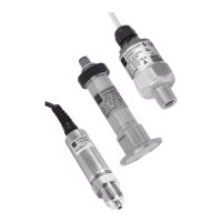
Cerabar T
Endress+Hauser 7
Electrical connection (switch output)
P01-PMP13xxx-04-xx-xx-xx-003
1 Plug M 16 x 1.5 (DIN 43650/A), ½ NPT
2 Plug M 12 x 1
R External load, e.g. relay, programmable logic controller, distributed control system
For electrical connection provided by customer use only shielded cable
PMP131 Electrical connection: Analog-/voltage output
P01-PMP131xx-04-xx-xx-xx-001
1 Plug M 16 x 1,5 (DIN 43650/A), ½ NPT and plug DIN 43 650/C
2 Plug M 12 x 1
3 Cable (rd = red, wh = white, gn = green)
For electrical connection provided by customer use only shielded cable
Supply voltage PMC131
11 to 30 V DC
PMP131 and PMP135 (current output, 2-wire version)
• For non-hazardous areas: 12 to 30 V DC
• Ex i: no-load voltage ≤ 26 V DC, short-circuit current ≤ 100 mA, power consumption ≤ 0.8 W
PMP131 (voltage output, 3-wire version)
• 15...30 V DC
PMP131 and PMP135 (switch output)
• 18 to 32 V DC, current consumption without load < 20 mA, with reverse polarity protection
Residual ripple • Analog output: max. 5 % of supply voltage
• Switch output: max. 10 % of supply voltage
Cable entry → See Page 18, "Ordering information" section.
––
++
2–1+
3+
R
R
18...32 V18...32 V
3
2
1
1
2
1+
2-
3
–
–
–
+
+
+
+
+
PE
–
rd
bk
wh
gn
3+
3-
2-
1+
1+
2+
15...30 V
15...30 V
15...30 V
0...10 V
0...10 V
0...10 V
1
2
3

 Loading...