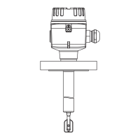
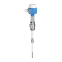
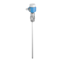
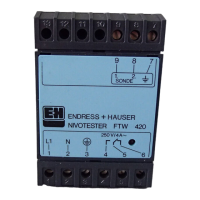
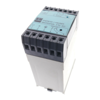
Liquiphant FTL31
Endress+Hauser 7
Electronic version 3-wire DC-
PNP
3-wire DC-PNP is preferably used in conjunction with programmable logic controllers (PLC), DI
modules as per EN 61131-2. Positive signal at the switch output of the electronics (PNP).
Voltage source: non-hazardous contact voltage or Class 2 circuit (North America).
M12 connector
Depending on the analysis of the switch outputs, the device works in the MAX (maximum safety) or
MIN (minimum safety) mode.
A cable is optionally available for order, see "Accessories" section (→ 27).
Electrical connection Operating mode
M12 connector MAX MIN
A0022901
A0021417
K
Yellow LED (ye) not lit
Yellow LED (ye) lit
external load
Function monitoring with M12 connector
Using a two-channel analysis, function monitoring of the sensor can be implemented in addition to
level monitoring, e.g. per relay switch, PLC, AS-i Bus I/O module, …).
When both outputs are connected, the MIN and MAX outputs assume opposite states when the
device is operating fault-free (XOR). In the event of an alarm condition or a line break, both outputs
are deenergized.
Connection for function monitoring with antivalence
Yellow LED
(ye)
Red LED
(rd)

 Loading...


