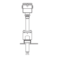
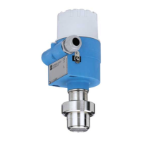
Liquipoint T FTW 31, FTW 32
Endress + Hauser 5
Input
Measured variable Resistance change between two conductors caused by the presence or absence of a conductive
product.
Measuring range
(application)
The measuring range is dependent on the mounting location of the probes.
Rod probes can have a max. length of 4000 mm and rope probes up to 15 000 mm.
Input signal Probes covered => a measurable current is flowing between the probes.
Probes uncovered => there is no measurable current flowing between the probes.
Output
Electronic insert FEW 52
(DC-PNP)
Output signal
Three-wire direct current version
Preferred in conjunction with programmable logic controllers (PLC).
Positive signal at the switch output of the electronics (PNP).
The output is blocked after the level limit is reached.
L00-FTW3xxxx-15-05-xx-en-001
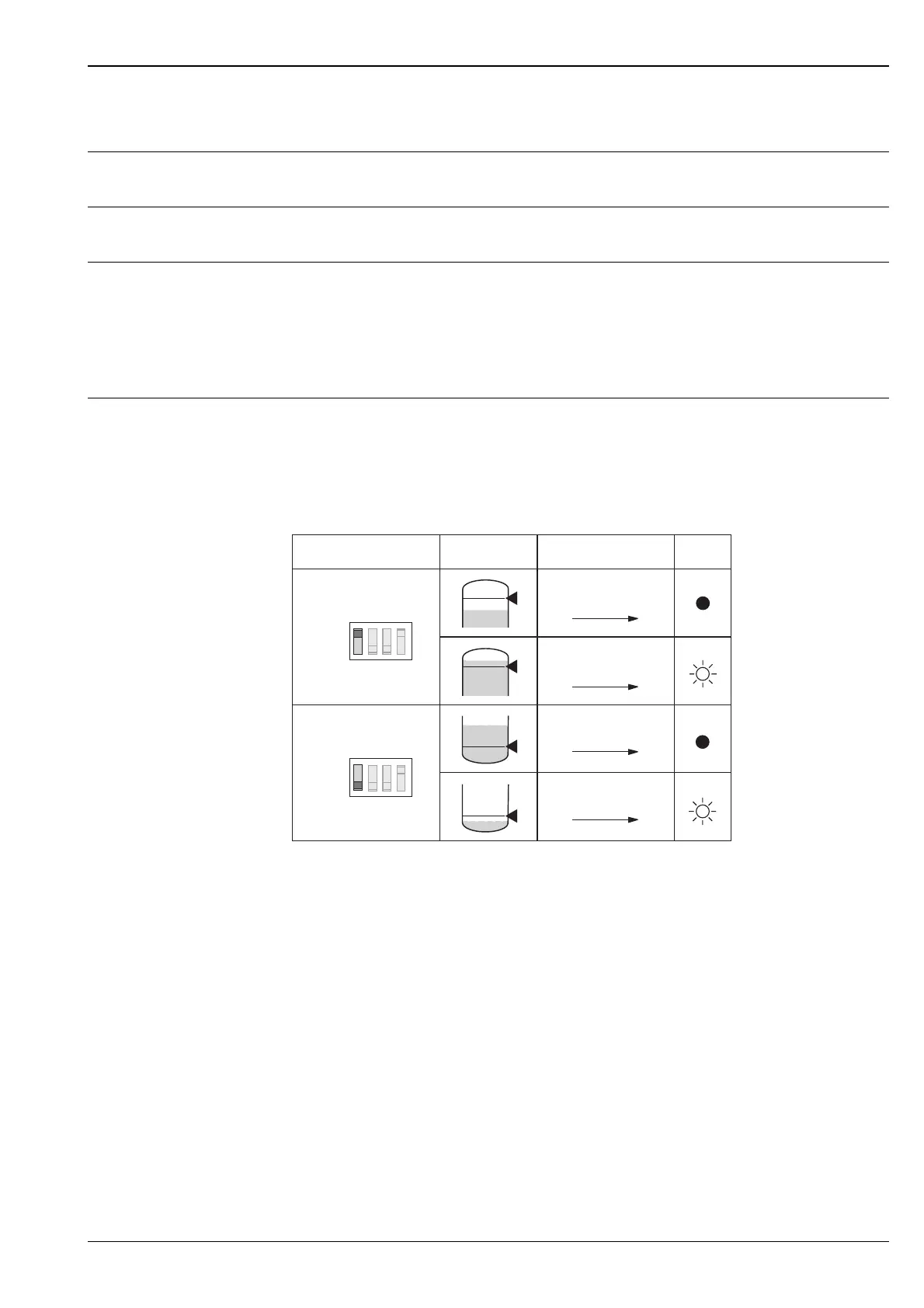
*1 = load current (connected); *2 residual current (disconnected); *3 LED not lit; *4 LED lit
See also Electrical connection on page 8.
If the probe is covered and the red LED flashes continuously, the next more sensitive measuring
range has to be set. This ensures a safe switch point even if the conductivity of the medium varies
slightly.
Fail-safe mode
Selecting the correct fail-safe mode ensures that the output always runs in quiescent current
fail-safe.
•
Maximum fail-safe: the output voltage is 0 V if the switch point is exceeded
(probe covered), a fault occurs or the power supply fails.
•
Minimum fail-safe: the output voltage is 0 V if the switch point is undershot
(probe uncovered), a fault occurs or the power supply fails.
Switching delay
A switching delay of 2.0 s can be activated or deactivated via a DIL switch.
If the switching delay is set to 0 s, the device switches after approx. 0.3 s.
I
L
< 100 µA
< 100 µA
L+
1 3
1 3
L+
1 3
+
1 3
I
L
Max.
Min.
MAX
MIN
rd
*
2
*
4
*
1
*
3
Fail-safe mode Switch point Output signal
 Loading...