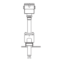
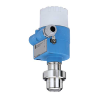
Liquipoint T FTW 31, FTW 32
6 Endress + Hauser
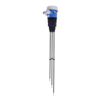
Measuring ranges
A total of four measuring ranges (100 Ω; 1 kΩ; 10 kΩ; 100 kΩ) can be set via two DIL switches
(SENS). The setting on delivery is 100 kΩ.
L00-FTW3xxxx-15-05-xx-xx-001
Signal on alarm
In the event of a power failure or a damaged probe: < 100 µΑ
Load
The load is switched via a transistor (PNP).
Cycled overload and short-circuit protection,
continuous ≤ 200 mA (short-circuit proof).
Residual voltage at transistor at I
max
< 2.9 V
Electronic insert FEW 54
(relay)
Output signal
AC/DC connection with relay output
When connecting a device with high inductance, a spark barrier must be fitted to protect the relay
contact. A fine-wire fuse (load-dependent) protects the relay contact in the event of a short-circuit.
Both relay contacts switch simultaneously.
L00-FTW3xxxx-15-05-xx-en-002
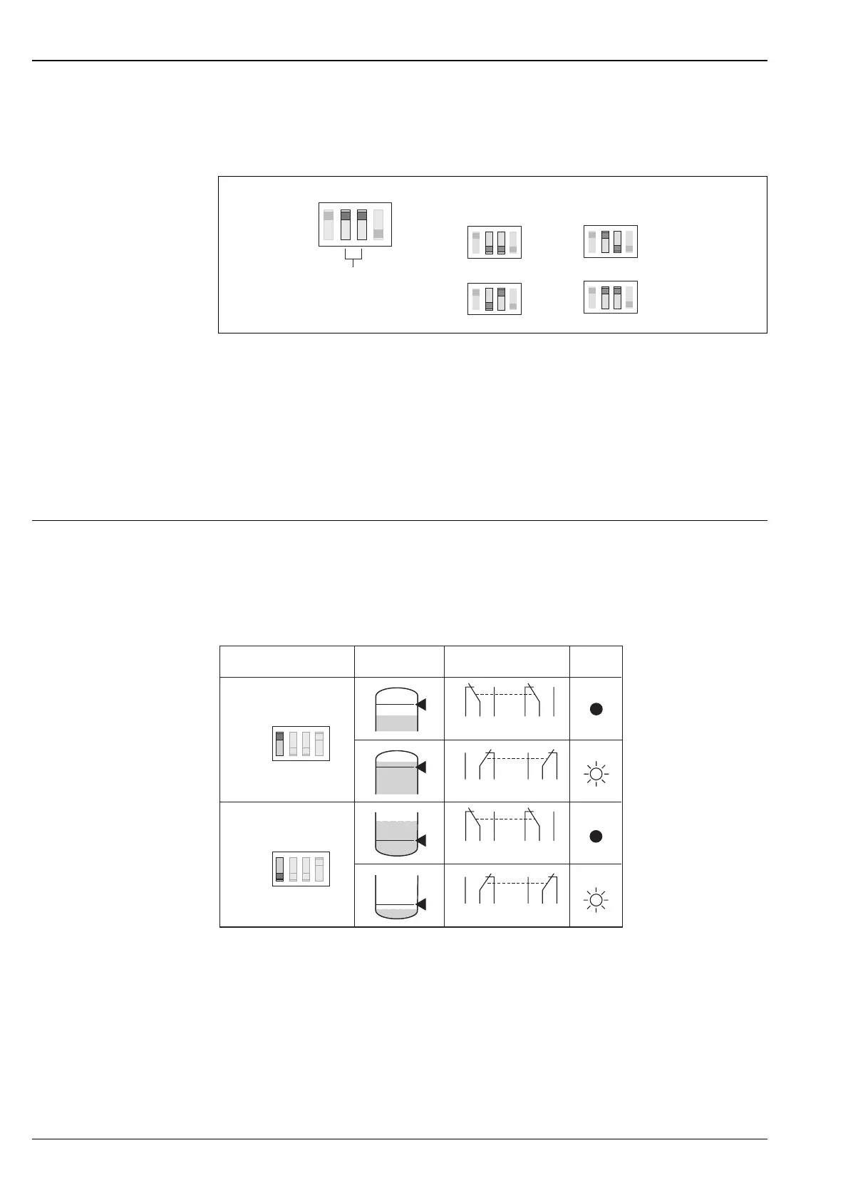
*1 = relay energised; *2 relay de-energised; *3 LED not lit; *4 LED lit
See also Electrical connection on page 9.
If the probe is covered and the red LED flashes continuously, the next more sensitive measuring
range has to be set. This ensures a safe switch point even if the conductivity of the medium varies
slightly.
MAX
MIN
2 s
0 s
SENS = 100 - 100kΩΩ
100 Ω
1 kΩ
10 kΩ
100 kΩ
*
2
*
1
354
354
687
687
354
354
687
687
Max.
Min.
MAX
MIN
rd
*
4
*
3
Fail-safe mode Switch point Output signal
 Loading...