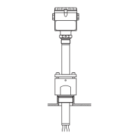
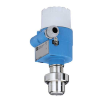
Liquipoint T FTW 31, FTW 32
8 Endress + Hauser
Electronic insert FEW 58
(NAMUR)
Output signal
For connecting to isolating amplifiers acc. to NAMUR (IEC 60947-5-6)
Output signal jump from high to low current on limit (H-L-edge).
Fail-safe mode
Selecting the correct fail-safe mode ensures that the relay always runs in quiescent current
fail-safe.
•
Maximum fail-safe: the output signal is < 1.0 mA when the switch point is exceeded
(probe covered), a fault occurs or the power supply fails.
•
Minimum fail-safe: the output signal is < 1.0 mA when the switch point is undershot
(probe uncovered), a fault occurs or the power supply fails.
Measuring ranges
A total of four measuring ranges (100 Ω; 1 kΩ; 10 kΩ; 100 kΩ) can be set via two DIL switches
(SENS). The setting on delivery is 100 kΩ.
L00-FTW3xxxx-15-05-xx-xx-001
Switching delay
A switching delay of 2.0 s can be activated or deactivated via a DIL switch.
If the switching delay is set to 0 s, the device switches after approx. 0.3 s.
Load
Refere to "Technical Data" date sheet of the connected isolating amplifier acc. to
NAMUR (IEC 60947-5-6)
Cable monitoring For probes without an electronic insert, an additional printed circuit board must be installed in the
housing, which enables cable monitoring. It is always switched or connected between rod/rope
1 and 2.
!
Note!
When using switching units (transmitters) that do not support cable monitoring, these must be
removed.
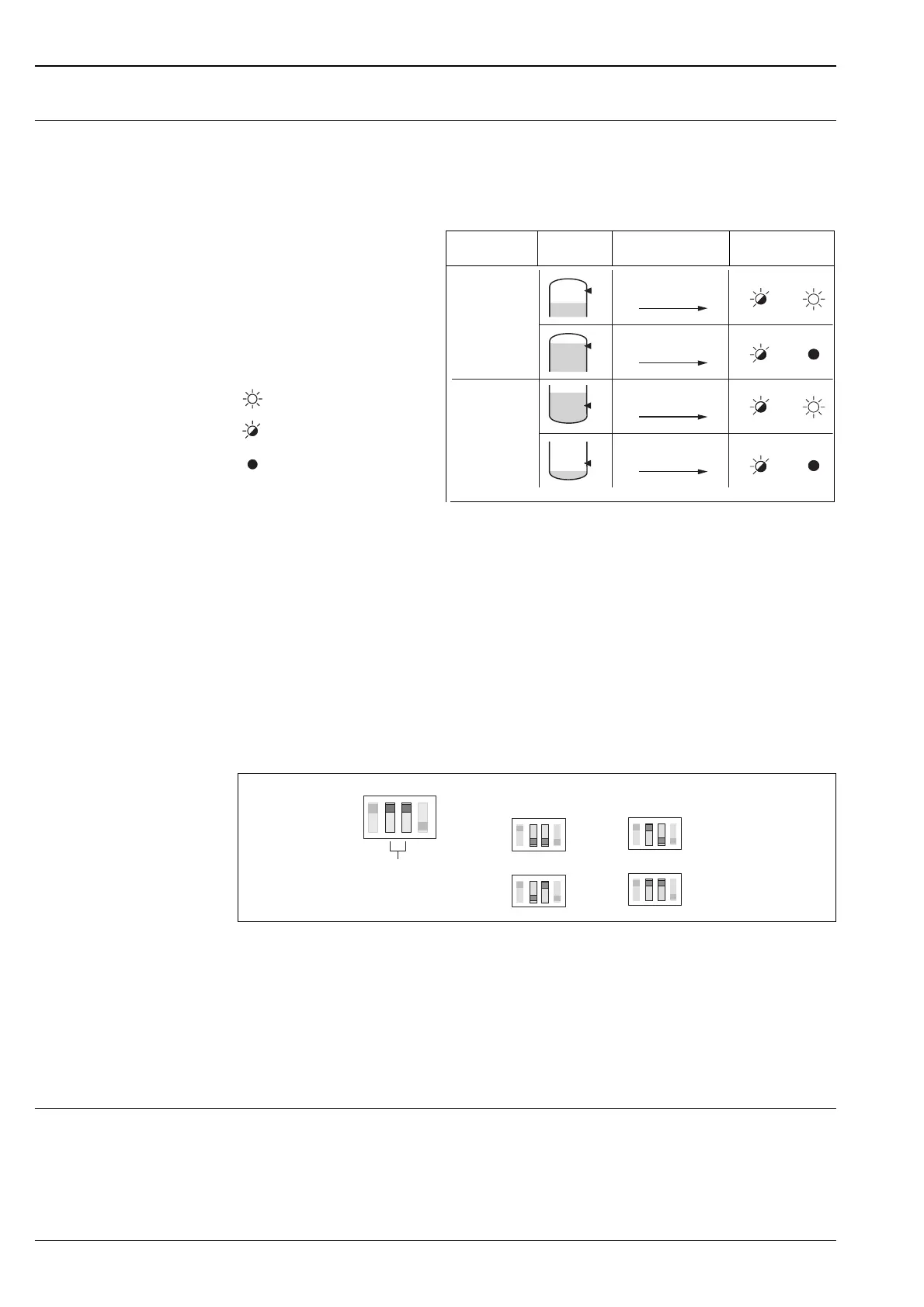
Fail-safe
circuit
Level Output signal LEDs
gn ye
L00-FTL5xxxx-07-05-
xx-xx-002
= lit
= flashes
= unlit
L00-FTW3xxxx-04-05-xx-xx-006
Max.
Min.
+
2 1
+
2 1
+
2 1
+
2 1
2.2 …
6.5 mA
2.2 …
6.5 mA
0.4 …
1.0 mA
0.4 …
1.0 mA
MAX
MIN
2 s
0 s
SENS = 100 - 100kΩΩ
100 Ω
1 kΩ
10 kΩ
100 kΩ
 Loading...