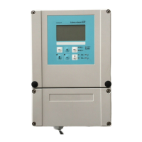
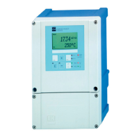
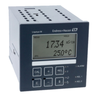
Liquisys M CCM223/253 Electrical connection
Endress+Hauser 21
5.3 Electrical connection, version 2
The wiring diagram shows the connections of a device equipped with all the options. The
connection of the sensors to the various measuring cables is explained in more detail in
the "Measuring cables and sensor connection" section.
A0001904
11 Electrical connection of the transmitter (version 2)
A pH/ORP input (optional) * Auxiliary voltage of terminal 85/86 can be used
B Sensor CCS120 J Alarm (current-free contact position)
C Auxiliary voltage output K Relay 1 (current-free contact position)
D Signal output 1, total chlorine L Relay 2 (current-free contact position)
E Signal output 2, temperature, pH or ORP M Relay 3 (current-free contact position)
F Binary input 1 (hold/cleaning) N Relay 4 (current-free contact position)
 Loading...
