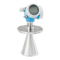
Micropilot FMR53, FMR54
40 Endress+Hauser
Flange size Number of screws Tightening torque
JIS
10K 50A 4 40 to 60 Nm
10K 80A 8 25 to 35 Nm
10K 100A 8 35 to 55 Nm
10K 150A 8 75 to 115 Nm
Free-space installation in
vessel
Rod antenna (FMR53)
Alignment
• Align the antenna so that it is perpendicular to the product surface.
• A marking is provided on the flange (at a point between the flange holes) or the gland to aid the
alignment. This marking must be aligned towards the tank wall as much as possible.
A
B
90°
90°
90°
90°
90°
90°
90°
90°
90°
90°
A0018974
Depending on the device version the marking may be a circle or two parallel lines.

 Loading...


