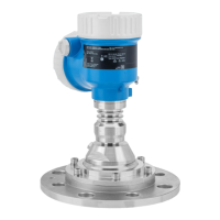
Micropilot FMR67B PROFINET with Ethernet-APL
16 Endress+Hauser
Metal deflector plates, installed at an angle to scatter the radar signals, help prevent interference
echoes.
Vertical alignment of antenna axis
Align the antenna so that it is perpendicular to the product surface.
The maximum reach of the antenna can be reduced, or additional interference signals can
occur, if the antenna is not installed perpendicular to the product.
Radial alignment of the antenna
Based on the directional characteristic, radial alignment of the antenna is not necessary.
Installation instructions Horn antenna 65 mm (2.56 in)
Information about the mounting nozzle
The maximum nozzle length H
max
depends on the nozzle diameter D.
Maximum nozzle length H
max
as a function of the nozzle diameter D
D H
max
80 to 100 mm (3.2 to 4 in) 1 700 mm (67 in)
100 to 150 mm (4 to 6 in) 2 100 mm (83 in)
≥ 150 mm (6 in) 3 200 mm (126 in)
In the case of longer nozzles, reduced measuring performance must be expected.
Please note the following:
• The end of the nozzle must be smooth and free from burrs.
• The edge of the nozzle should be rounded.
• Mapping must be performed.
• Please contact the manufacturer's support department for applications with nozzles that are
higher than indicated in the table.
Horn antenna 65 mm (2.56 in) with alignment unit
UNI flanges with an integrated alignment unit are available for the horn antenna 65 mm (2.56 in).
An angle of inclination of up to 15 ° in all directions can be set for the antenna axis using the
alignment unit. The alignment unit is used to optimally align the measuring signal to the bulk solids.
A0048891
9 Horn antenna with alignment unit

 Loading...