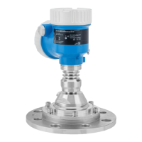
Micropilot FMR67B PROFINET with Ethernet-APL
Endress+Hauser 19
The maximum length of the nozzle H
max
depends on the nozzle diameter D
D H
max
min. 80 to 100 mm (3 to 4 in) 1 450 mm (57 in)
100 to 150 mm (4 to 6 in) 1 800 mm (71 in)
≥ 150 mm (6 in) 2 700 mm (106 in)
In the case of longer nozzles, reduced measuring performance must be expected.
Please note the following:
• The end of the nozzle must be smooth and free from burrs.
• The edge of the nozzle should be rounded.
• Mapping must be performed.
• Please contact the manufacturer's support department for applications with nozzles that are
higher than indicated in the table.
Purge air connection
In applications with strong dust emissions, the integrated purge air connection can prevent the
antenna from becoming clogged. Pulse operation is recommended.
A0046593
11 Antenna with purge air adapter
1 Purge air connection NPT 1/4" or G 1/4"
Purge air pressure range
• Pulse operation :
Max. 6 bar (87 psi)
• Continuous operation:
200 to 500 mbar (3 to 7.25 psi)
Purge air connection
• Tool:
• Open-ended wrench 13 mm (G 1/4")
• Open-ended wrench 14 mm (NPT)
• Open-ended wrench 17 mm (NPT "adapter")
• Min. torque: 6 Nm (4.4 lbf ft)
• Max. torque: 7 Nm
• Always use dry purge air
• In general, purging should only be performed to the extent necessary as excess purging can
cause mechanical damage (abrasion)
Beam angle
The beam angle is defined as the angle α where the energy density of the radar waves reaches half
the value of the maximum energy density (3 dB width). Microwaves are also emitted outside the
signal beam and can be reflected off interfering installations.

 Loading...