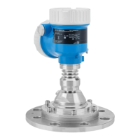
Micropilot FMR67B PROFINET with Ethernet-APL
Endress+Hauser 21
PTFE, flush mount 80 mm (3 in) antenna, α 3 °
W = D × 0.05 D W
5 m (16 ft) 0.25 m (0.82 ft)
10 m (33 ft) 0.50 m (1.64 ft)
15 m (49 ft) 0.75 m (2.46 ft)
20 m (66 ft) 1.00 m (3.28 ft)
25 m (82 ft) 1.25 m (4.10 ft)
30 m (98 ft) 1.50 m (4.92 ft)
35 m (115 ft) 1.75 m (5.74 ft)
40 m (131 ft) 2.00 m (6.56 ft)
45 m (148 ft) 2.25 m (7.38 ft)
50 m (164 ft) 2.50 m (8.20 ft)
60 m (197 ft) 3.00 m (9.84 ft)
70 m (230 ft) 3.50 m (11.48 ft)
80 m (262 ft) 4.00 m (13.12 ft)
100 m (328 ft) 5.00 m (16.40 ft)
125 m (410 ft) 6.25 m (20.51 ft)
Special mounting
instructions
External measurement through plastic cover or dielectric windows
• Dielectric constant of medium: ε
r
≥ 10
• The distance from the tip of the antenna to the tank should be approx. 100 mm (4 in).
• Avoid installation positions where condensate or buildup can form between the antenna and the
vessel
• In the case of outdoor installations, ensure that the area between the antenna and the tank is
protected from the weather
• Do not install any fittings or attachments between the antenna and the tank that could reflect the
signal
The thickness of the tank ceiling or the dielectric window depends on the ε
r
of the material.
The material thickness can be a full multiple of the optimum thickness (table); it is important to
note, however, that the microwave transparency decreases significantly with increasing material
thickness.
Optimum material thickness
Material Optimum material thickness
PE; ε
r
2.3 1.25 mm (0.049 in)
PTFE; ε
r
2.1 1.30 mm (0.051 in)
PP; ε
r
2.3 1.25 mm (0.049 in)
Perspex; ε
r
3.1 1.10 mm (0.043 in)

 Loading...