Electrical connection Nivector FTI26
16 Endress+Hauser
6 Electrical connection
6.1 Connection conditions
The measuring device has two modes of operation:
• Maximum point level detection (MAX): e.g. for overfill prevention
The device keeps the electrical switch closed as long as the sensor is not yet covered by
medium.
The device keeps the electrical switch closed as long as the sensor is not yet covered by
medium or the measured value is within the process window.
• Minimum point level detection (MIN): e.g. Dry running protection
The device keeps the electrical switch closed as long as the sensor is covered by medium.
The device keeps the electrical switch closed as long as the sensor is covered by medium or
the measured value is outside the process window.
Choosing the MAX or MIN mode of operation ensures that the device switches in a safety-
oriented manner even in an alarm condition, e.g. if the power supply line is disconnected. The
electronic switch opens if the point level is reached, if a fault occurs or if the power fails
(quiescent current principle).
6.2 Connecting the measuring device
• Supply voltage 12 to 30 V DC
• In accordance with IEC/EN61010 a suitable circuit breaker must be provided for the
measuring device.
• Voltage source: Non-hazardous contact voltage or Class 2 circuit (North America).
• The device must be operated with a 500 mA fine-wire fuse (slow-blow) which is suitable for
DC current in accordance with IEC 60127-2.
• Depending on the analysis of the switch outputs, the measuring device works in the MAX or
MIN modes.
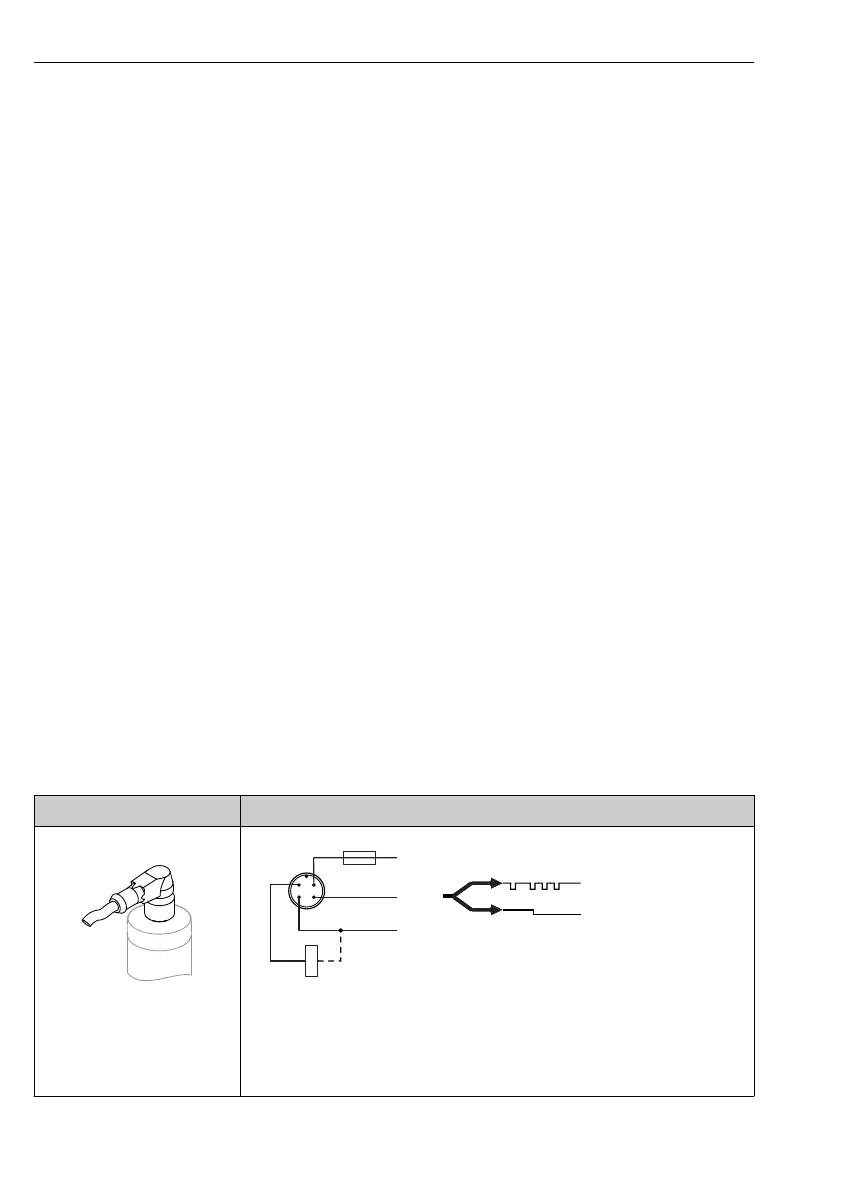
6.2.1 Operation with IO-Link
Electrical connection IO-Link with a switch output
M12 plug
L–
L+
C/Q1
2
1
3
4
SIO
IO-Link
0.5 A
K1
Q2
A0034411
1 Supply voltage +
2 DC-PNP (Q2)
3 Supply voltage -
4 C/Q1 (IO-Link communication or SIO mode)

 Loading...