Prosonic Flow 92
Endress+Hauser 7
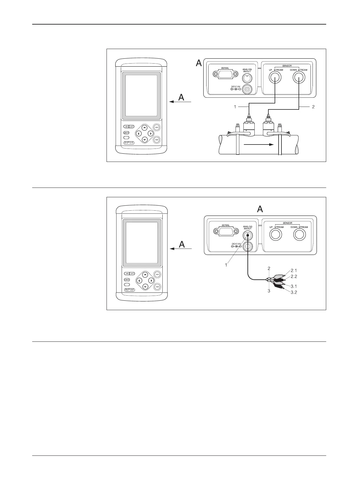
Electrical connection:
sensor cable connection
A = View A
– 1 = Upstream sensor cable
– 2 = Downstream sensor cable
Electrical connection:
analog input/output
connection
A = View A
– 1 = Analog input/output connector
– 2 = Analog output wires; 2.1 = red (+); 2.2 = black (-)
– 3 = Analog input wires; 3.1 = red (+); 3.2 = black (-)
Potential equalisation Special measures for potential equalisation are not necessary.
F06-92xxxxxx-04-06-06-xx-001
F06-92xxxxxx-04-06-06-xx-001
 Loading...


