Planning
and Installation
Inlet and Outlet Sections
An undisturbed flow profile is a pre-
requisite for accurate vortex flow
measurement. This can be ensured
through sufficient inlet and outlet pipe
sections.
•
Inlet sections: min. 10 x DN
•
Outlet sections: min. 5 x DN
Where flow disturbances such as pipe
elbows, reducers, valves, etc. are
located upstream of the vortex meter,
longer upstream pipe sections are
required.
If possible any valves should be
installed after the flowmeter.
Note:
Where two or more disturbances are lo-
cated upstream of the meter, the longest
recommended upstream pipe section is
to be observed.
Flow Conditioner
With limited space and large pipes, it is
not always possible to have the inlet
sections given above.
The specially developed perforated
plate flow rectifier can reduce the inlet
path to 10 x DN.
The flow rectifier is held between two
piping flanges and centred with the
flange bolts.
It rectifies distorted flow profiles effi-
ciently with very little pressure loss.
Flow conditioner pressure loss
calculation:
∆p [mbar] = 0.0085 ⋅ ρ [kg/m
3
] ⋅ v
2
[m/s]
•
Example with steam:
p = 10 bar abs.; t = 240 °C ⇒ ρ = 4.39 kg/m
3
v = 40 m/s
∆p = 0.0085 ⋅ 4.39 kg/m
3
⋅ (40 m/s)
2
=
59.7 mbar
•
Example with H
2
O condensate (80 °C)
ρ = 965 kg/m
3
; v = 2.5 m/s
∆p = 0.0085 ⋅ 965 kg/m
3
⋅ (2.5 m/s)
2
=
51.3 mbar
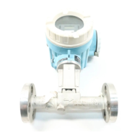
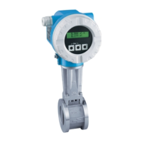
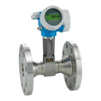
The following installation recommendations are to be observed when installing
Prowirl in the pipeline. In order to maintain the specified accuracy for all fluids and
process conditions, the inner diameters of the meter or meter flange and the
process piping should be identical. Specification of the correct process piping inner
diameter or standard (DIN, ANSI Schedule 10/40/80 etc.) will avoid the need for
calculated K factor corrections.
Inlet
Outlet
Reduction
Expansion
90° elbow
or T-piece
2 x 90° elbows
2 x 90° elbows
3-dimensional
Control valve
With flow
conditioner
ti031y06
Inlet and outlet piping requirements
5
 Loading...
