Measuring Ranges,
Nominal Diameters
Selecting the Nominal Diameter
The following are used to determine the
measuring range and nominal diameter:
•
Tables (e.g. for saturated steam
measuring ranges)
•
Measuring range diagrams
(for superheated steam, gases, and
liquids)
•
"Applicator" software
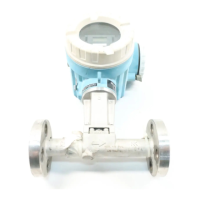
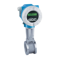
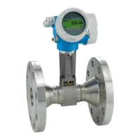
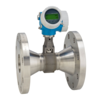
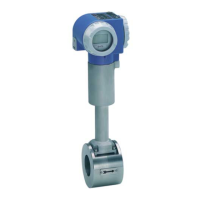
The Prowirl vortex flowmeter determines
the volumetric flow under operating
conditions (e.g. m
3
/h), i.e. the effective
volume at a particular operating press-
ure (e.g. 20 bar).
Gas volumes are highly dependent on
pressure and temperature.
Gas quantities are, therefore, usually
given at standard temperature and
pressure (Nm
3
at 1.013 bar, 0 °C)
and steam quantities in kg or tons.
Calculating the volumes under operat-
ing conditions is done using the
following equations and tables (see
following pages).
"Applicator" Design Software
All important transmitter data are
contained in this E+H software for the
most efficient design of the measuring
system. The equations used for calculat-
ing the properties of steam are the
latest available according to IAPS
(International Association for the
Properties of Steam).
The Applicator software makes light
work of the following calculations:
•
Conversion of the operating volume of
gas into a corrected volume
•
Conversion to the mass flow of steam
using temperature and/or pressure
variables
•
Calculation with viscosity included
•
Calculation of pressure drop accross
the flowmeter
•
Simultaneous display of calculations
for various nominal diameters
•
Determining measuring ranges
The software runs on any IBM
compatible PC.
Calculations
Flow Values
The actual values for maximum and
minimum flow depend mainly on the
following factors:
•
The Reynolds number (describing the
flow condition) must be above 4000
•
The fluid density determines the upper
and lower flow limits as described
below (“Minimum and Maximum
Volumetric Flow Q
min
/Q
max
”)
•
Cavitation must be avoided (for liquids)
On the following pages different tables
are given for various typical applica-
tions. Those tables can be used as a
guideline for a first estimate of the
measuring range. Please contact your
Endress+Hauser sales organisation for
exact dimensioning of the meter for your
specific application.
Minimum and Maximum Volumetric Flow (Q
min
/Q
max
)
Fluid density: 1 kg/m
3
≤ ρ ≤
12.0 kg/m
3
•
DN 15: Q
min
=
di
2
• 0.0226
√
ρ
Q
max
= di
2
• 0.130
•
DN 25...300: Q
min
=
di
2
• 0.017
√
ρ
Q
max
= di
2
• 0.212
Fluid density: ρ
>
12.0 kg/m
3
•
DN 15: Q
min
=
di
2
• 0.022
√
ρ
Q
max
= di
2
• 0.130 for ρ ≤ 33 kg/m
3
Q
max
=
di
2
• 0.746
√
ρ
for ρ > 33 kg/m
3
•
DN 25...300: Q
min
=
di
2
• 0.017
√
ρ
Q
max
=
di
2
• 0.746
√
ρ
where
ρ = density in kg/m
3
Q = volumetric flow in m
3
/h
di = internal diameter of pipe in mm
8
 Loading...
