12
DESCRIPTION OF OPERATION
General
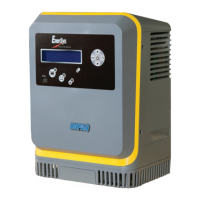
NexSys
®
+ chargers are microprocessor-controlled. The processor calculates the battery’s
capacity so that the charging profile can be automatically adapted to the battery’s actual state
over a wide range of capacities. NexSys+ chargers adapt to the battery’s capacity and its
discharge level.
NexSys+ chargers are set to charge NexSys
®
, GelBloc, flooded and sealed lead-acid batteries
within the range of the cell and ampere-hour rating marked on the nameplate. Attempting to
charge other battery designs with this charger could cause damage to the battery.
Starting the Charge Cycle
When a battery is connected to the charger, the control board senses the voltage and after a
short delay, the charger starts charging the battery.
Charging Current
Charging current is determined by the battery voltage and state of the charge condition. Charging
current declines automatically as battery voltage rises during the charge. As the battery charges,
the graphical display will output various charge parameters including the percentage of battery
capacity.
AC Power Fail
If the AC power fails with a battery connected to the charger during a charge cycle, the charger
will reset and start a new charge cycle when power is restored. All charger settings as well as
the time and date are preserved.
Series Charging
In series charging, the voltages of both batteries add up and must match charger’s nameplate
DC Volts rating. The charger’s amp-hour rating must be equal to each battery’s ampere-hour
rating. Charge cycle will not start unless both batteries are connected.