EasyManua.ls Logo

EnerSys NexSys+ NIP1 User Manual

EnerSys NexSys+ NIP1
47 pages
To Next Page IconTo Next Page
To Previous Page IconTo Previous Page
Page #27 background image
NexSys
®
+
Owner’s Manual
AM-NXSPLUS-OM
Rev AC October 2018
26
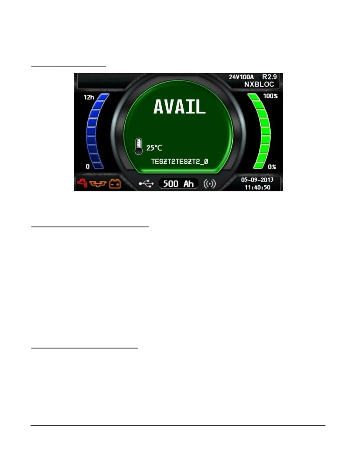
End of Charge Display
End of Charge without Equalization
The green complete LED comes on after proper end of charge. The green complete LED is on
and the display shows AVAIL. The display alternates between:
Total charging time.
Amp-Hours restored to the battery.
L2 0 1 0 24-3 6 -48V U S11
Any other lit LED indicates a problem during charging. Please refer to paragraph Control Panel
for more information.
If the battery remains plugged in and refresh charge has been enabled, refreshes will occur to
maintain an optimal charge.
The battery is now ready for use. Push the ON/OFF button before unplugging the battery.
End of Charge with Equalization
An Equalize charge can be started manually or automatically.
Manual Equalization Start
1. At the end of charge (green LED on or flashing), press on the <EQUALIZE> button. The
equalize button can also be pressed any time during the charge and an equalize charge
will be started after charging is complete.

Table of Contents

Question and Answer IconNeed help?

Do you have a question about the EnerSys NexSys+ NIP1 and is the answer not in the manual?

EnerSys NexSys+ NIP1 Specifications

General IconGeneral
Input Frequency50/60 Hz
Efficiency>90%
Cooling MethodFan cooled
Storage Temperature-40°C to 70°C
ChemistryLead
Protection FeaturesOver voltage, Over current, Over temperature, Reverse polarity, Short circuit
Communication InterfaceCAN bus
Operating Temperature-20°C to 50°C
DimensionsVaries by model
WeightVaries by model

Summary

Important Safety Instructions

Safety Warnings and Precautions

Covers general safety advice, handling, and environmental conditions for charger operation.

Technical Information

Part Number and Model Identification

Explains the structure of part numbers and UL model numbers for charger identification.

Charger Specification Codes

Details letter codes for output power, cabinet size, voltage, AC line, and charge profiles.

Technical Parameters and Certifications

Describes serial number, battery type, capacities, AC/DC specs, and certifications (CEC, cULus).

Installation Procedures

Location and Cabinet Mounting

Guidelines for charger placement, environmental considerations, and physical installation.

Electrical Connections and Grounding

Instructions for connecting input power and ensuring proper grounding of the charger unit.

Electrical Protection and Wiring

AC Circuit Protection and Breaker/Fuse Chart

Details branch circuit protection requirements and provides a chart for breaker/fuse sizing.

Glossary of Terms

Charging Profile and Battery Technology Definitions

Explains terms like Wi-iQ, Charging Profile, TPPL, Gel-Bloc, IONIC, NXBLOC, NXSTND, NXFAST, VRLA.

Charging Operation Modes

Defines Equalization Charging, Block Out Time, and Refresh Charging operations.

Operation Overview

General Charger Functionality

Describes microprocessor control, battery compatibility, and charging adaptation.

Charge Cycle Initiation and Dynamics

Explains starting a charge, charging current behavior, and AC power failure handling.

Series Charging Configuration

Details requirements for charging multiple batteries in series.

Abbreviations and Acronyms

Common Abbreviations and Acronyms

Lists and defines common terms used throughout the manual.

Operating Instructions

Battery Compatibility and Profiles

Lists compatible battery voltages and available charging profiles.

Wi-iQ Device Integration

Explains the function and benefits of the Wi-iQ device for battery monitoring.

Control Panel

Control Panel Layout and Indicators

Identifies and describes the buttons and LED indicators on the control panel.

Menu Access

Main Menu Navigation

Explains how to access and navigate the main menu and its functions.

Logs

Charge Cycle Memorization

Describes how to display and view details of past charge cycles.

Memorization Data Fields

Lists and defines the data recorded for each charge cycle.

Status

Status Counters and Fault Reporting

Explains how to view charger status counters and fault types.

Charger

Charger Configuration Information

Details how to display and interpret charger configuration settings.

Configuration and Settings

USB Functions and Software Updates

Accessing USB for software updates and managing charger software.

System Settings Configuration

Adjusting date, time, language, region, and display settings.

Display Themes and Screen Saver

Customizing display appearance and configuring screen saver settings.

Daylight Saving and Password Access

Configuring daylight saving time and password entry for service menus.

Battery Charging Procedures

Charger Idle Display and Status

Shows information when the charger is ready but not connected to a battery.

Initiating and Managing Charge Cycles

Covers starting, delayed start, and countdown displays for charging.

Wi-iQ Device Integration in Charging

Explains how Wi-iQ device integration affects the charging process.

Charge Completion and Equalization

End of Charge Status Display

Describes the display and LEDs upon charge completion.

Equalization Charging Modes

Details manual and automatic equalization start procedures.

Troubleshooting and Fault Codes

Fault Display and Code Interpretation

Explains how faults are displayed and lists common fault codes, causes, and solutions.

Maintenance and Service

Basic Maintenance and Service Warnings

Provides guidance on cleaning, safety precautions, and contacting service.

Mounting Dimensions

1 kW Cabinet Mounting Dimensions

Provides detailed dimensions for mounting 1 kW 3-bay and 6-bay cabinets.

3.5 kW Cabinet Mounting Dimensions

Provides detailed dimensions for 3.5 kW 2, 4, 6, and 8-bay cabinets.

Technical Specifications

1 kW Charger Specifications

Detailed table of AC input and DC output specifications for 1 kW models.

3.5 kW Charger Specifications

Detailed table of AC input and DC output specifications for 3.5 kW models.

Maintenance Log

Factory Settings Modifications Log

A log for recording changes made to factory settings.

Service Log Entries

A log for recording performed service tasks and dates.

Related product manuals