4.8.
Power supply connection
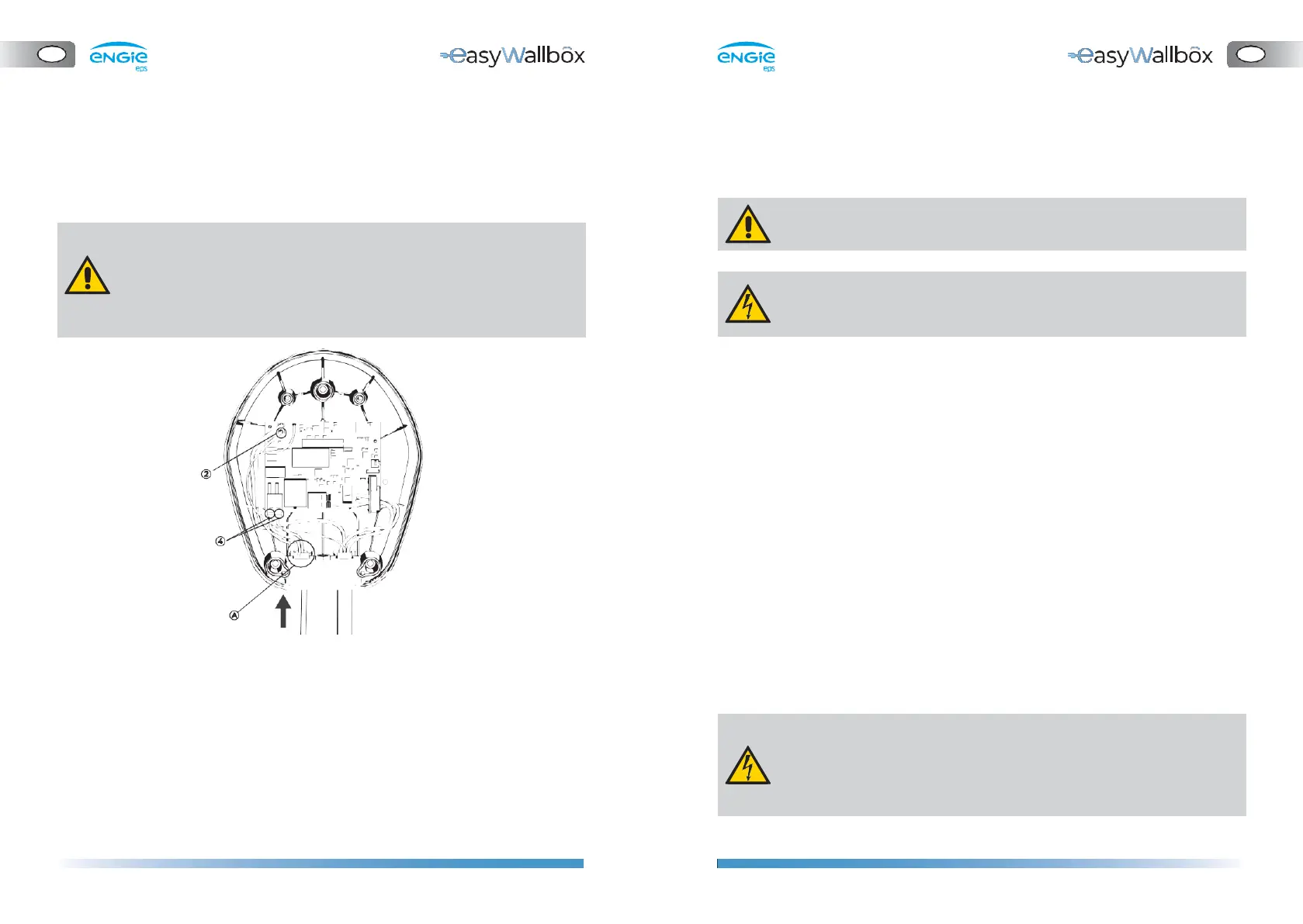
⚫ Connect the earthing wire to the J3 ‘Faston’ terminal (2).
⚫ We recommend using FEMALE 6.3 x 0.8 ‘Fastons’, better if with
restraint.
⚫ Insert the power supply wires through the cable gland (A)
⚫ Shorten the connection wires to the appropriate length (avoid
leaving too much cable margin). The protective conductor PE must
be longer than the other conductors.
⚫ Connect the cables to the J1 tool-free ‘push-lock’ terminals (4).
Connect Line (L) and Neutral (N) as indicated on the board.
⚫ We recommend using flexible cables with the following max.
section:
- 6 mm2
⚫ The power supply to easyWallbox must be installed on a dedicated
thermal-magnetic miniature circuit breaker (MCB) mounted in the
service panel to protect the electrical circuit.
⚫ When dimensioning the MCB, the higher ambient temperatures in
the control cabinet must also be taken into account.
⚫ When dimensioning the MCB, the prospective short-circuit current
should be considered. As an indicative value 5kA could be considered
but a precise evaluation must be done before installation. The
maximum interrupting capacity of the MCB must be greater than
the evaluated prospective short-circuit current.
⚫ The MCB must be in line with the section of the wires.
⚫ The installation must incorporate a dedicated and adequate residual
current device (RCD/ fault-current circuit breaker). An RCD with at
least Type A must be used since easyWallbox has an internal DC
fault current monitoring of ≥ 6 mA.
⚫ Be aware that local regulations may be applicable and may vary
depending on your region/country of residence. easyWallbox must
be installed according to the local regulations.
Risk of electric shock.
Before starting installation, ensure that easyWallbox is not
connected to any power supply. Any installation, maintenance
and dismantling operation should only be done when the power
supply is switched off on your service panel.
 Loading...