4.9.
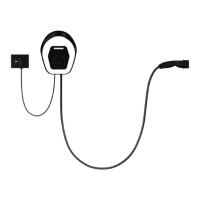
Installation of the Dynamic Power Management sensor
(optional step)
If the Dynamic Power Management is not required, please go to
chapter 4.10.
To connect the current sensor:
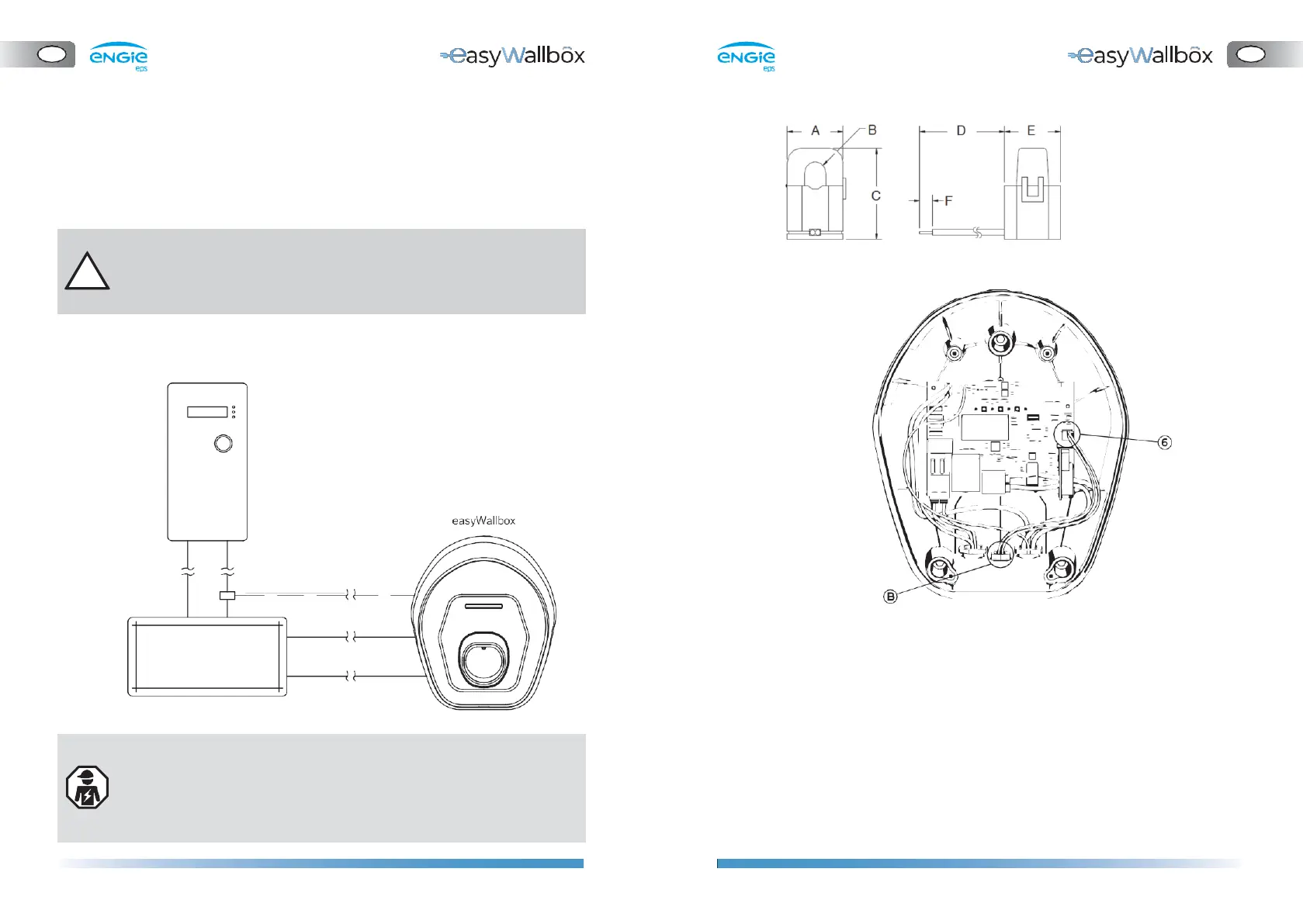
A = 25.5 mm
B = 10.2 mm
C = 40 mm
D = 5.91 mm
E = 26.5 mm
F = 6.1 mm
Please read the following instructions carefully before installing the
dedicated Dynamic Power Management (DPM) sensor.
a.
The current sensors must be attached to a single meter output
wire
b.
The sensor has a hinge and locking snap which allows attachment
without interrupting the live wire.
c.
Join the current sensor wires and twisted cable (recommended
section 0.5 mm2).
d.
Bring the twisted cable near to
easyWallbox
.
e.
Insert the twisted cable through the cable gland (B).
f.
Connect the twisted cable to the J7 ‘push-in’ spring terminals (6)
without tools. There is no particular requirement about cabling
position on the terminal.
-
The connection of the Dynamic Power Management sensor
requires installation by a professional.
-
We recommend contacting qualified personnel or service for any
questions or doubts concerning easyWallbox’s use, installation,
and maintenance.
easyWallbox can work without Dynamic Power Management.
In this case, the installation of a dedicated sensor is not necessary
but avoidance of blackouts is not guaranteed.