4.10.
Setting the rotary switch
The installer in Mode 3 should correctly set the Rotary Switch following
the instructions:
Table
1
– Rotary Switch default DPM current
4.11.
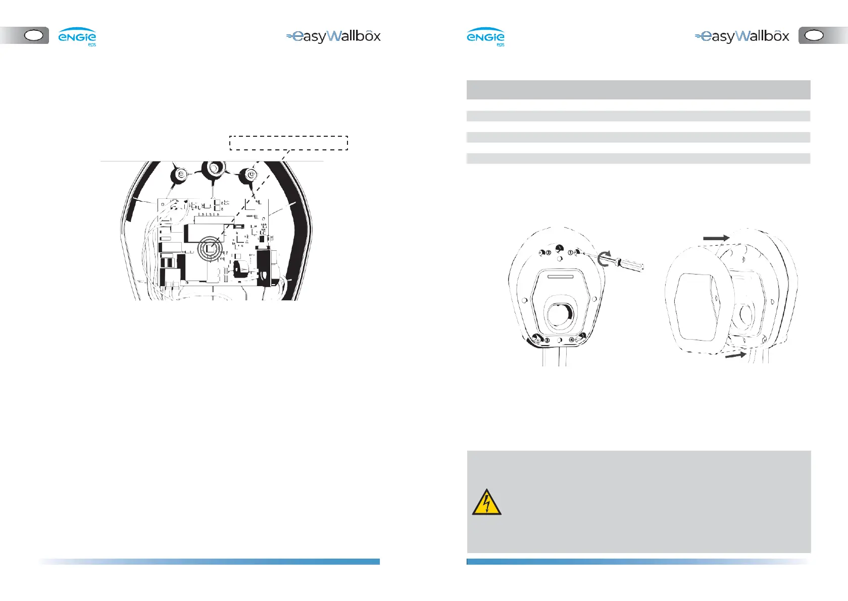
Case reassembly
1.
If the DPM sensor is not installed, choose POSITION
1.
2.
If the parametrisation of the DPM has been configured via app,
choose POSITION 2 and configure it via
easyWallbox
Up!
(chapter
4.12).
3.
As an alternative, configure the DPM operation and limits in
accordance with the user’s energy supply contract, following
Table
1,
Rotary Switch default DPM current
1.
Reassemble the front panel
of
easyWallbox
2.
Reposition the aesthetic cover
A list of meanings of the Rotary Switch positions follows:
⚫ POSITION 0: Not allowed (reserved)
⚫ POSITION
1:
DPM is always turned off
⚫ POSITION 2: DPM can be enabled or disabled via the easyWallbox Up!
(see chapter 4.12) or My easyWallbox (see chapter 5.2)
⚫ POSITION 3 to POSITION 9: DPM operation depends on the
corresponding max power values [kW] set by default
3.
Once
easyWallbox
has been mounted on the wall and connected
to the power supply, switch on power supply on your service panel.
- Before connecting to a power supply, make sure that easyWallbox
is installed correctly, with a proper earth connection and in
compliance with local and international standards.
- ENGIE Eps does not assume any liability for damage caused by
non-compliant installation of the device. Installers in Mode 3
and Mode 2 with Power Upgrade are responsible for
completing the installation at a state-of-the-art technical level
and in compliance with applicable regulations.