IQ 7 / IQ 7+ / IQ 7X / IQ 7A Installation and Operation
© 2020 Enphase Energy Inc. All rights reserved. 141-00044-02
Step 8: Complete Installation of the Junction Box
A. Connect the Enphase Q Cable into the junction box.
B. Refer to the wiring diagrams on page 39 for more information. Q Cable uses the following
color code:
NOTE: The Q Cable internally rotates L1, L2, and L3 to provide balanced 400 VAC
(three-phase), thus alternating phases between microinverters.
NOTE: Minimise the number of unused Q Cable connectors with three-phase systems.
When cable connectors are left unused on a three-phase system, it creates a phase
imbalance on the branch circuit. If multiple cable connectors are skipped over multiple
branch circuits, the imbalance can multiply.
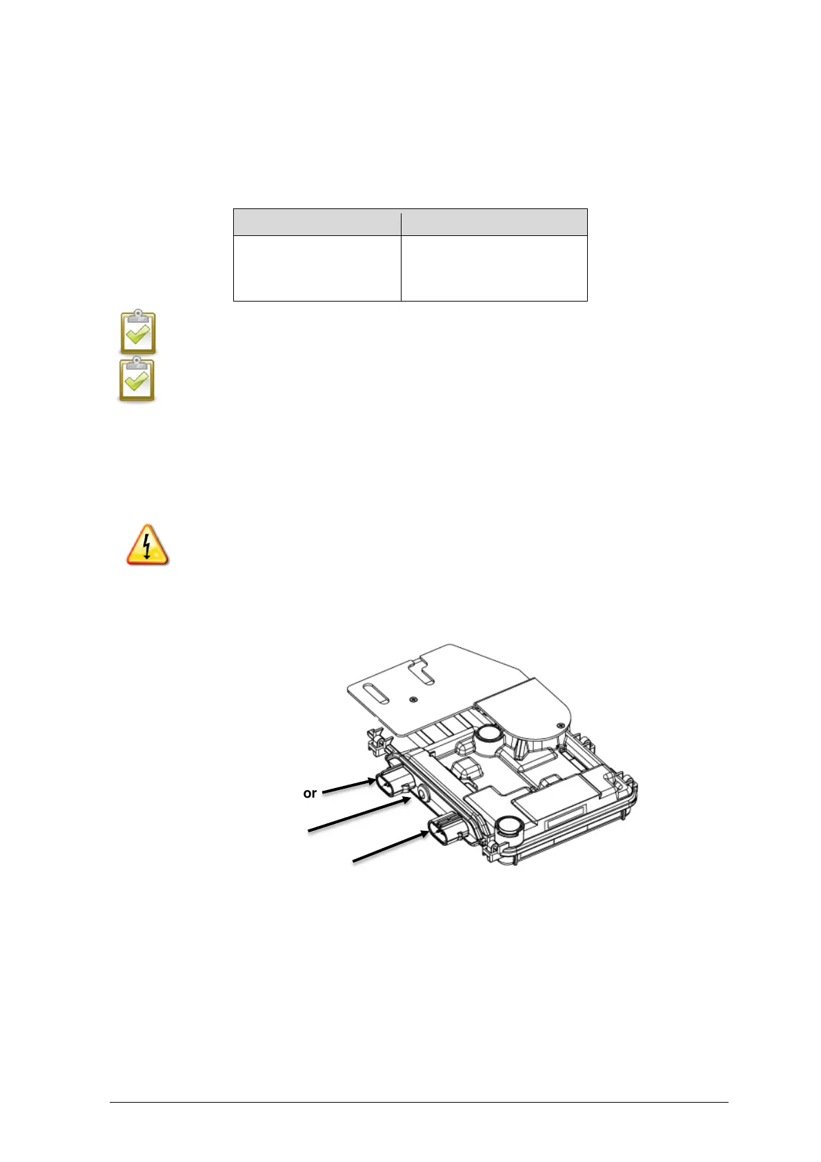
Step 9: Connect the PV Modules
WARNING: Electrical shock hazard. The DC conductors of this photovoltaic system are
ungrounded and may be energized.
A. Connect the DC leads of each PV module to the DC input connectors of the
corresponding microinverter.
B. Check the LED on the connector side of the microinverter. The LED flashes six times
when DC power is applied.
C. Mount the PV modules above the microinverters.