IQ 7 / IQ 7+ / IQ 7X / IQ 7A Installation and Operation
© 2020 Enphase Energy Inc. All rights reserved. 141-00044-02
Step 3: Mount the Microinverters
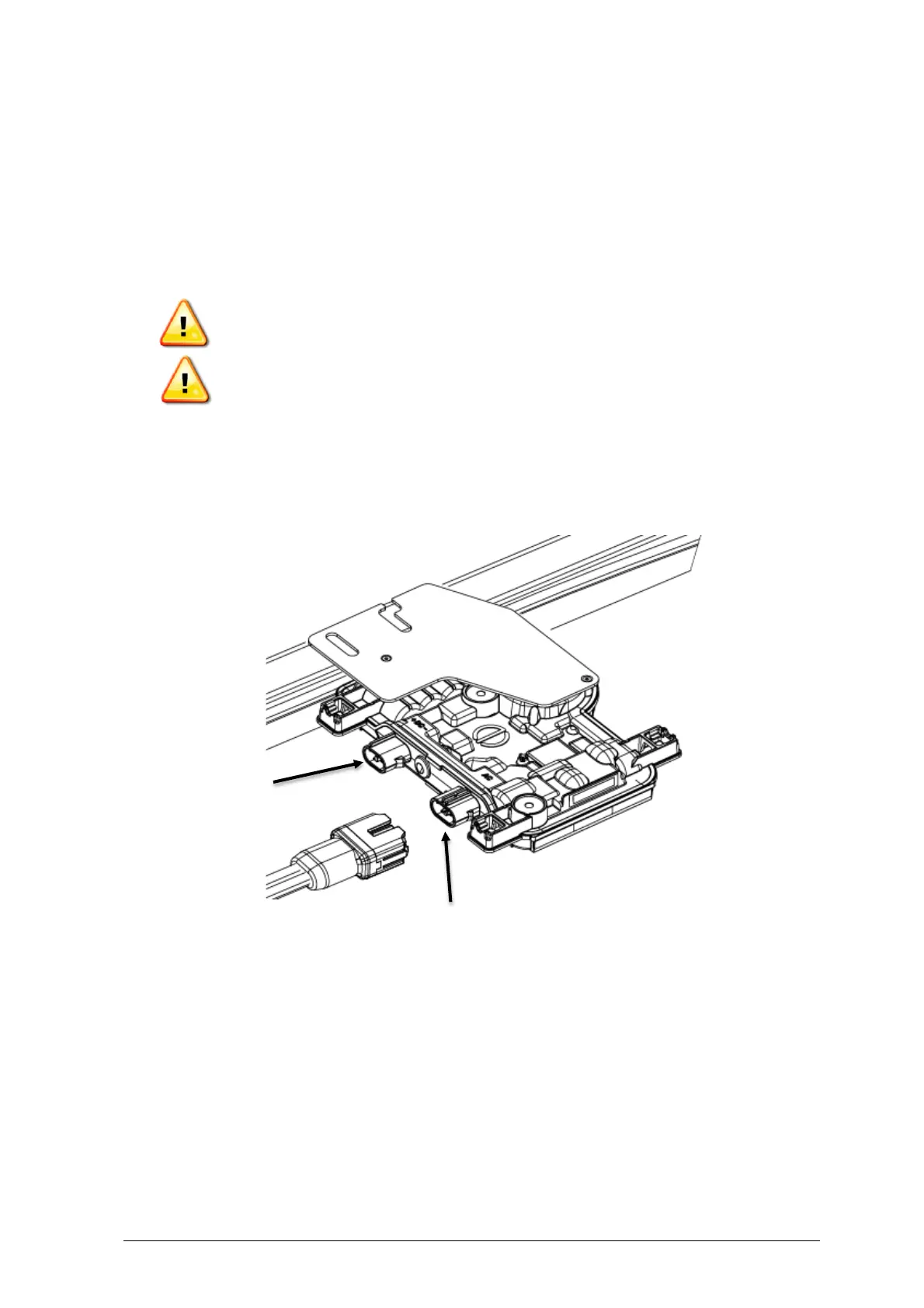
A. If the Enphase DC bulkhead connectors are not already attached to the microinverters,
attach them now. Make sure they are fully seated.
B. Mount the microinverter bracket side up (as shown) and under the PV module,
away from rain and sun. Allow a minimum of 1.9 cm between the roof and the
microinverter. Also allow 1.3 cm between the back of the PV module and the top of the
microinverter.
WARNING: Install the microinverter under the PV module to avoid direct exposure to
rain, UV and other harmful weather events. Do not mount the microinverter upside
down.
WARNING: IQ7A installs are not recommended with bi-facial modules, and use of
such may impact the limited warranty.
C. Torque the microinverter fasteners as follows. Do not over torque.
• 6 mm mounting hardware: 5 N m
• 8 mm mounting hardware: 9 N m
• When using UL 2703 mounting hardware, use the manufacturer’s
recommended torque value