IQ8MC/IQ8AC/IQ8HC Installation and Operation Manual
14 © 2023 Enphase Energy Inc. All rights reserved. September 2023
IOM-00029-1.0
Step 1: Position the IQ Cable
A. Plan each cable section to allow connectors on the IQ Cable to align with each PV module. Allow
extra length for slack, cable turns, and any obstructions.
B. Mark the approximate centers of each PV module on the PV racking.
C. Lay out the cabling along the installed racking for the AC branch circuit.
D. Cut each section of cable to meet your planned needs.
WARNING: When transitioning between rows, secure the cable to the rail to prevent cable
damage or connector damage. Do not put the connector at the microinverter under tension.
Step 2: Position the junction box
A. Verify that the AC voltage at the site is within range.
*Nominal voltage range can be extended beyond nominal if required by the electricity network operator.
B. Install a junction box/AC isolator at a suitable location.
C. Provide an AC connection from the junction box/AC isolator back to the electricity network using
equipment and practices in accordance with local electrical codes and standards.
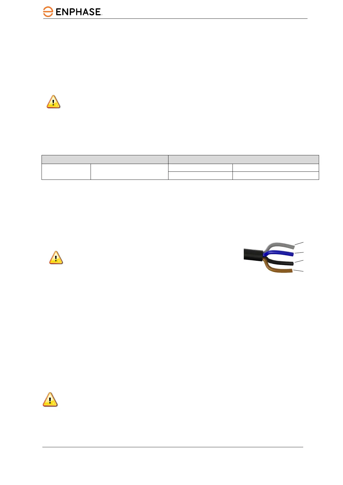
D. For multi-phase installations, verify the IQ Cable wiring colour codes are correctly terminated: L1-
Brown, L2-Black, L3-Grey, N-Blue.
WARNING: Blue conductor in IQ Cable should be used only for
neutral connection. Incorrect termination may irrecoverably
damage any connected microinverters.
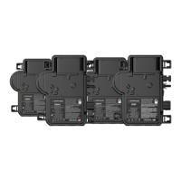
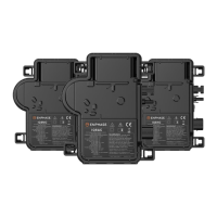
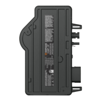
Step 3: Mount the microinverters
A. The microinverters should be mounted beneath the modules either horizontal bracket side up or
vertical orientation to the module and must be protected from direct exposure to rain, UV, and other
harmful weather events. Please refer to the image below for clearance requirements during vertical
mounting.
• Always place the microinverter under the PV module, protected from direct exposure to rain,
sun, and other harmful weather events. Allow a minimum of 19 mm ( 3/4") between the roof
and the microinverter. Also, allow 13 mm (1/2") between the back of the PV module and the
top of the microinverter.
• For vertical mount, also maintain at least 300 mm (12") clearance from the edges of the PV
module to protect the microinverter from direct exposure to rain, UV, and other harmful
weather events.
WARNING: Install the microinverter under the PV module to avoid direct exposure to rain, UV, and
other harmful weather events. Do not mount the microinverter upside down.
B. Torque the microinverter fasteners as follows. Do not over-torque.
• 6 mm mounting hardware: 5 N m
• 8 mm mounting hardware: 9 N m
L1 to N 184 to 276 VAC*