DATE :
08/08/2023
SHEET:
1 of 1
SCALE:
NTS@A4
DRAWING No:
EN-IQ8-1PHN
DRAWING Name:
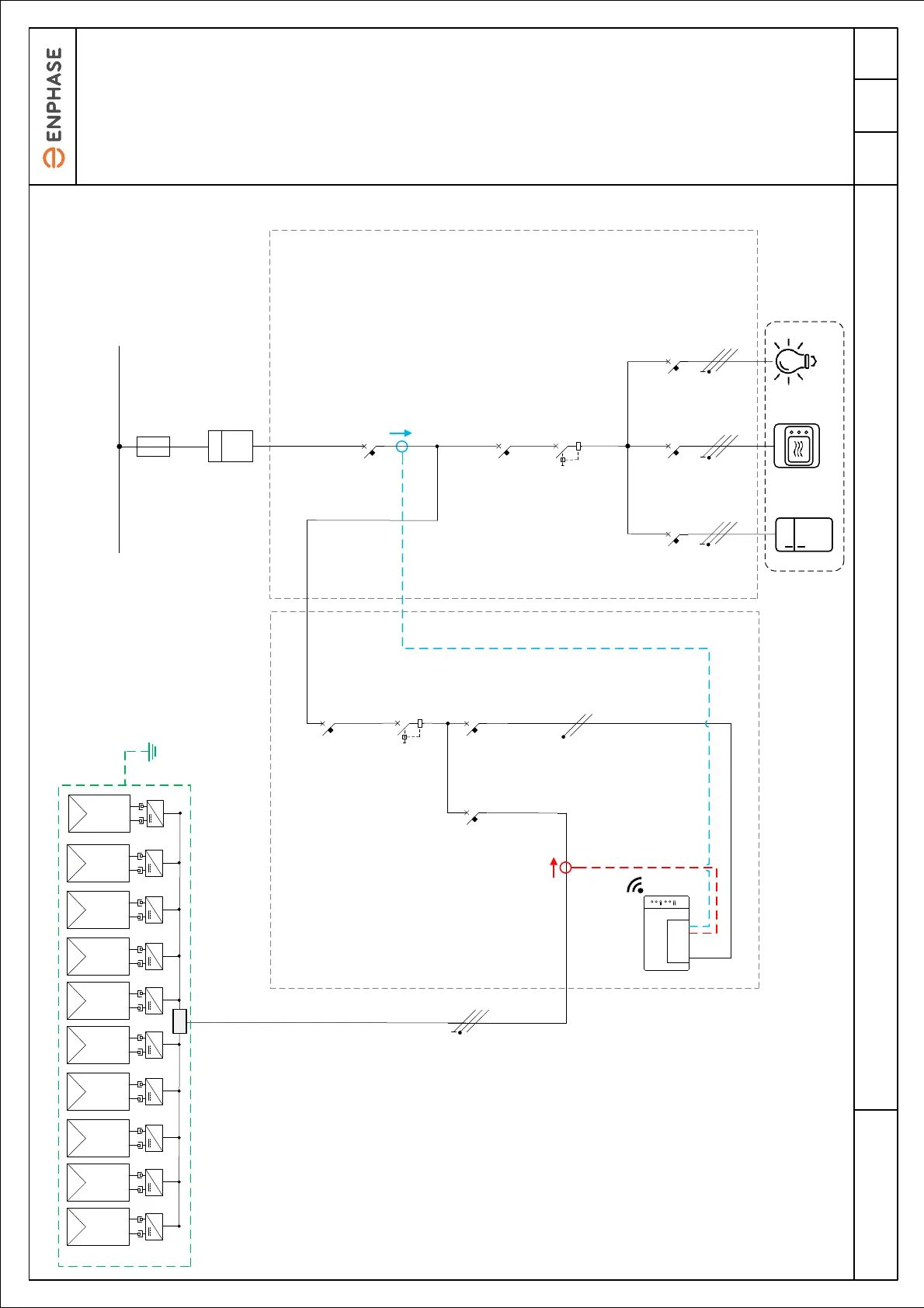
Electrical diagram example: Single-phase IQ8 Series Microinverters (IQ8MC or IQ8AC or IQ8HC) Grid Tied PV System
Q1
1PH+N
Q2
1PH+N
Qn
1PH+N
Consumption measurement
CTs installed on Line
Conductor
AC Cable 3 Core
(L1, N, PE)
6 mm² Minimum recommended
conductor size, see note 4
~ ~ ~ ~~ ~~ ~~
AC Cable 2x 2.5mm² (L1, N)
~
JB
MCB
1PH+N
20A
MCB
1PH+N
6A
Main Breaker
1PH+N
PV Sub panel Main Panel
RCD - Consumption
1PH+N
See note 7
MCB - Consumption
1PH+N
MCB - Production
1PH+N
40 A
RCD - Production
1PH+N
40A, 30mA
See note 7 and 8
Production measurement
CT installed on Line
Conductor
Maximum 8 microinverters per
IQ Cable Section
Single-phase IQ Cable 2x 2.5 mm²
(L1, N)
Array structure
earthing where
required
See note 6
NOTES:
1.These schematics are examples
only. These schematics provide
recommendations to assist the
system designer and installer.
2.The design and installation of
the photovoltaic power plant must
be carried out in accordance with
local electrical standards in the
country of installation and must be
carried out by competent
personnel.
3.Before installing any PV
equipment, check the phase-to-
neutral voltage at the point of
connection. The operating voltage
must be within a range acceptable
for the 230 V microinverters.
4.The lengths and cross sections
of AC cable (between the end of
the IQ Cable and the electrical
panel) must be determined in
accordance with the electrical
standards in force in the country of
installation. It is recommended that
the voltage drop on this cable
does not exceed 1% and that
overall voltage drop in the PV
circuit from the point of connection
to the most remote microinverter
does not exceed 2%.
5.The 2.5 mm² IQ Cable is usually
protected by a 20 A B curve circuit
breaker.
6. The equipotential bonding
between PV module frames, array
mounting structure and the metal
microinverter mounting brackets
must be installed in accordance
with local electrical standards..
7. Surge protection devices (SPD)
and Residual Current Devices
(RCD) must be installed
accordance with local electrical
standards. Enphase microinverters
have an Internal surge protection.
8. Enphase microinverters have an
integrated High Frequency
transformer which provides
galvanic separation between DC
and AC parts. Where local
electrical standards require RCD
protection, a Type AC device can
be used.
9. Utility meter may be located
inside the main panel or as a
standalone device.
Maximum Microinverters per 20 A Circuit:
11x IQ8MC or 10x IQ8AC or 9x IQ8HC
(Maximum 16 A per phase)
Utility meter
See note 9
Utility meter
See note 9
kWhkWh
Public Electricity Network
(Grid Connection)
IQ Gateway
Metered
Communication
Gateway
LoadsLoads
Gateway internet connection:
- Ethernet LAN cable
- Wi-Fi
- Mobile Connect Cellular Modem
Gateway internet connection:
- Ethernet LAN cable
- Wi-Fi
- Mobile Connect Cellular Modem