Troubleshooting an Enphase System
2014 Enphase Energy Inc. August 2014
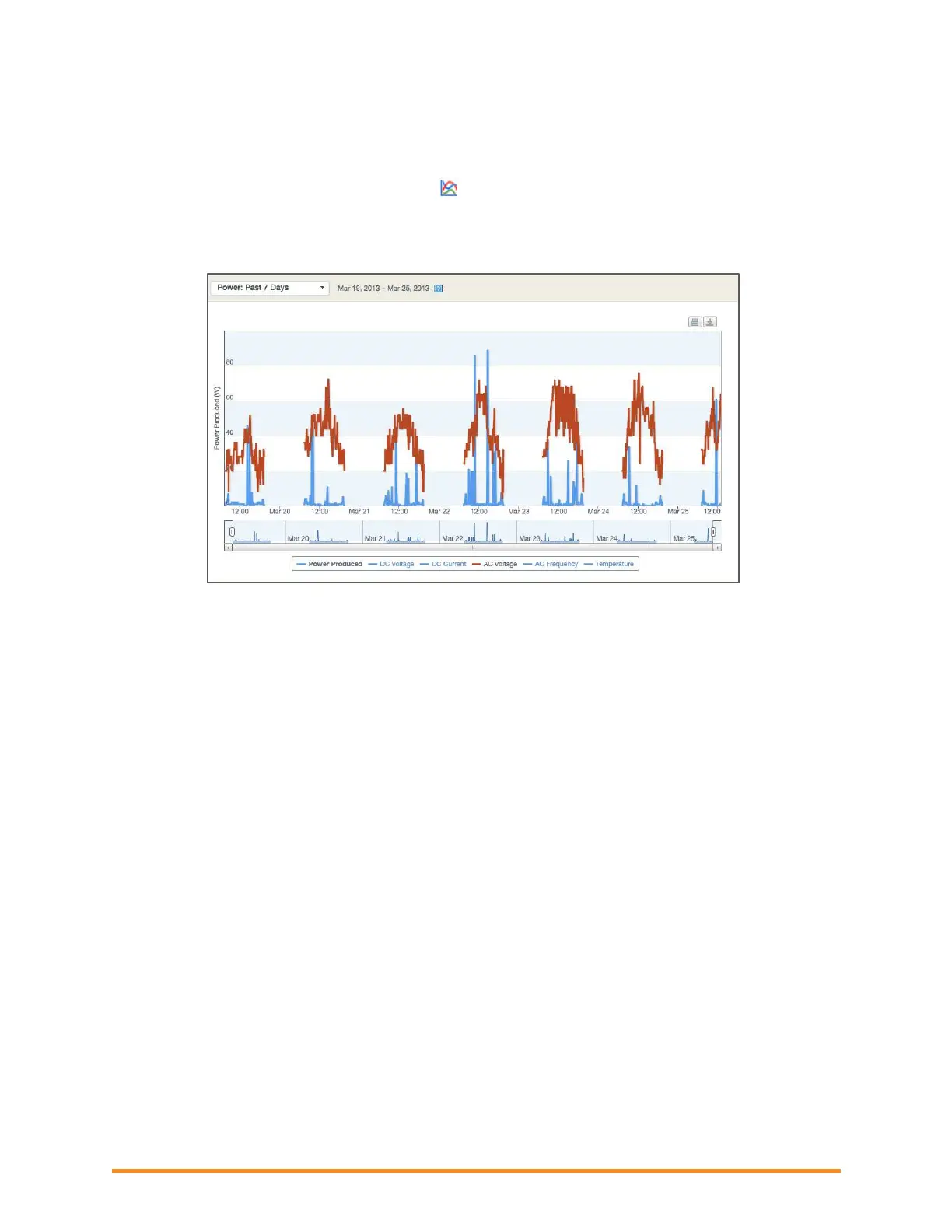
2. As an alternative, you can check AC voltage in Enlighten. To view the AC measurements:
Click on the module under review in the View tab.
In the pop-up, click the graph icon.
Click Power: Past 7 Days. The 7-day graph displays production in blue.
At the bottom of the graph, select AC voltage to display AC voltage in brown. Move the
cursor over the AC voltage and verify that AC voltage has been consistent and within range.
3. You can also select AC Frequency to view AC frequency readings.
4. Verify that the AC pigtail or cabling to the junction box is correctly terminated per wire color as
described in the Microinverter Installation and Operations Manual.
5. Verify that a circuit breaker with the correct amperage rating is installed and that the number of
termination poles is correct.
If the breaker is undersized, the branch may experience nuisance tripping at peak production
times.
If the breaker is oversized, the branch may have been damaged with too much current flow
through the microinverters.
6. Verify that the service entrance power is not coming from a 240 VAC “DELTA” or 240 VAC
“STINGER” secondary transformer.
7. Make sure that the site does not have undersized conductors, either to the Enphase branch circuit
or between the primary load center and the subpanel if a subpanel is installed.
If the array branch circuits land on a PV subpanel and there is additional wire run back to the
main service tie-in, you must perform additional voltage rise calculations. Enphase Energy
recommends that the total voltage rise on all wiring sections be 2% or less. This includes the
Enphase Engage Cabling, the homerun wiring from the junction box to the microinverter
subpanel, and the section from the microinverter subpanel to the main service panel or Point
of Common Coupling (PCC). Refer to the Calculating Voltage Rise Technical Brief at
enphase.com/support.